Lifting cup support

A technology for a cup holder and a lifting bracket, applied in the field of cup holders, can solve the problems of poor stability and clamping performance, large volume, complex structure, etc., and achieve the effect of reducing design difficulty and manufacturing cost, ensuring performance and simple structure

Inactive Publication Date: 2014-06-18
SHANGHAIK YANFENG JINQIAO AUTOMOTIVE TRIM SYSTEMS CO LTD
View PDF9 Cites 6 Cited by
  • Summary
  • Abstract
  • Description
  • Claims
  • Application Information

AI Technical Summary

Problems solved by technology

[0005] The purpose of the present invention is to provide a lifting cup holder, so as to solve the defects of the prior art that the cup holder itself has a large volume, many parts, complex structure, poor stability and clamping performance

Method used


Image

  • Lifting cup support
  • Lifting cup support
  • Lifting cup support

Examples


Embodiment Construction

[0027] The present invention will be further described below in conjunction with specific embodiments. It should be understood that the following examples are only used to illustrate the present invention but not to limit the scope of the present invention.

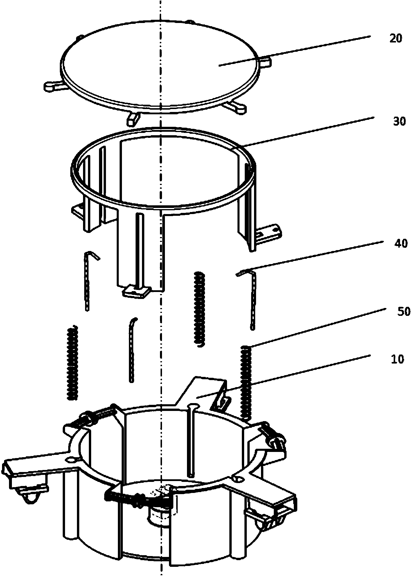
[0028] Such as Figure 3-Figure 9 Shown is a lifting cup holder according to a preferred embodiment of the present invention, which is shown as a trisection symmetrical structure centered on the central axis, including: a supporting shell 10, a tray 20, a lifting bracket 30, a pull cord 40 and Spring 50.

[0029] Wherein, the structure of tray 20 is as follows: Figure 4 As shown, it includes a substantially circular tray body 25, and the snap joint 21 (see Figure 8 ), and bolt joints 22 and pressure heads 23 extending from the outer periphery of the tray body 25 at regular intervals. In this embodiment, there are preferably three bolt joints 22 and pressure heads 23 respectively. Preferably, the upper surface of th...


PUM


Abstract

The invention provides a lifting cup support which comprises a tray, a lifting support, a supporting shell body, a spring and a pulling rope. The tray comprises a tray body, a clamping-connecting head, a bolt connector and a pressing head. The clamping-connecting head is arranged on the back face of the tray body, and the bolt connector and the pressing head extend out of the outer periphery edge of the tray body. The lifting support is arranged on the outer portion of the tray in a sleeved mode and comprises a decorating ring which extends in the periphery direction and an arm part which extends in the axial direction of the decorating ring, and the arm part further comprises a bending part and a first limiting groove. The supporting shell body is arranged on the outer portion of the lifting support in a sleeved mode and comprises a periphery wall which extends in the axial direction and a bottom face, an opening hole and a second limiting groove are formed in the periphery wall at intervals, and a lock piece matched with the clamping-connecting head is arranged on the bottom face. The spring is contained in the opening hole, and the top end of the spring abuts against the pressing head. One end of the pulling rope is connected with the bending part, and the other end of the pulling rope is connected with the bolt connector. Under the situation that the lifting cup support does not affect the appearance of a product, a small number of parts are used, the structure is simple, a cup support lifting function is achieved, designing difficulty and manufacturing cost are lowered, and performance stability is guaranteed.

Description

technical field [0001] The present invention relates to a cup holder, more particularly to a lifting cup holder. Background technique [0002] In order to meet the different needs of customers, the shape of cars is becoming more and more diverse, and the configuration functions are more humanized. For example, the car cup holder placed in the center of the car's auxiliary instrument or the center of the rear seat. In order to accommodate cups of different heights, the bracket (or side wall) of the cup holder is designed to be adjustable up and down. [0003] For example, patent CN200710169551.0 discloses a cup holder with lifting function, such as figure 1 As shown, the cup holder mainly includes a supporting shell 100 , a cup carrying tray 200 , a lifter shell 300 and a lifting unit 400 . The lifting unit 400 includes a main gear 410 hinged to the supporting shell 100 and the cup tray 200 respectively, and a driven gear 430 engaged between the main gear 410 and the rack 4...

Claims


Application Information

Patent Timeline
Patent Type & Authority Applications(China)
IPC IPC(8): B60N3/10
Inventor 陈涛
Owner SHANGHAIK YANFENG JINQIAO AUTOMOTIVE TRIM SYSTEMS CO LTD
Why Eureka
Try Eureka