Rotatable flange plate

A flange and shell technology, applied in the field of rotatable flanges, can solve the problems of signal interruption, inconvenience in production and life, irregularities, etc., and achieve the effect of convenient installation and convenient fixed installation.

Inactive Publication Date: 2014-06-18
XIAN ELITE ELECTRONICS IND
View PDF8 Cites 1 Cited by
  • Summary
  • Abstract
  • Description
  • Claims
  • Application Information

AI Technical Summary

Problems solved by technology

[0002] The shell of the traditional cable connector has a fixed flange for installation, and holes are opened at both ends of the flange. When fixing, it only needs to be fixed on the pre-prepared mounting frame with bolts or screws, and the hole position of the mounting frame After that, it can be firmly fixed by inserting screws or bolts. This fixing method is reliable and easy to disassemble. However, this kind of fixing is sometimes extremely inconvenient. Sometimes it is limi

Method used


Image

  • Rotatable flange plate

Examples


Embodiment Construction

[0010] The present invention will be further described below in conjunction with the accompanying drawings and specific embodiments.

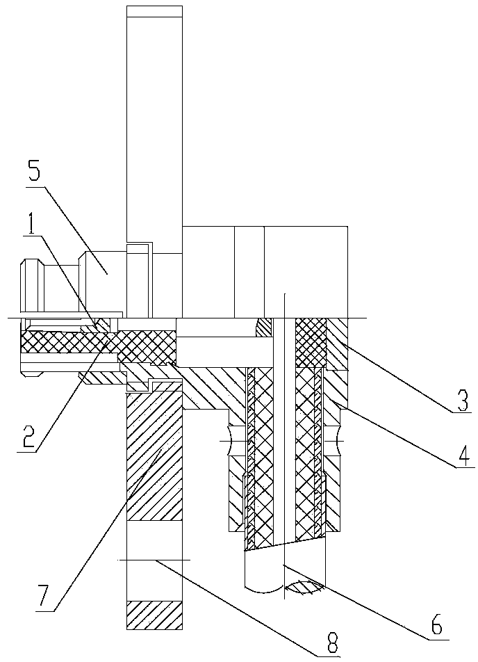
[0011] As shown in the drawings, a rotatable flange of the present invention includes a casing 4 and a flange 7 arranged on the casing 4, a screw is arranged on the casing 4, and a flange 7 is arranged on the casing 4. A screw hole matching the screw on the shell 4 is provided, and the flange 7 and the shell 4 are connected through the screw hole and the screw, so the flange can rotate on the shell. Mounting holes 8 for fixing the flange 7 and connectors are installed at both ends of the flange 7

[0012] A collar 5 is provided on the housing 4 . Rely on the collar 5 to clamp the flange 7 to prevent the flange 7 from unscrewing.

[0013] The assembly method of the present invention is: put the insulator 2 into the shell 4 and press fit it in place, and then press it into the socket 1 to ensure that the slotting direction of the socket is show...


PUM


Abstract

The invention discloses a rotatable flange plate comprising a housing and a flange disc arranged on the housing; the flange plate and the housing are connected through threads; the housing is provided with a clamp ring; because the flange plate and the housing is connected through the threads, the flange plate can rotate on the housing, and direction positions of flange plate mounting holes can be freely adjusted; when a connector is fixed, only the flange plate is adjusted and rotated so as to connect a hole position of a connector mounting rack; no matter mounting directions of the hole positions are regular or not, the flange plate can be rotated for installation, thereby providing great conveniences for fixation and installation of the connector.

Description

technical field [0001] The invention belongs to the structural field of flanges, and in particular relates to a rotatable flange. Background technique [0002] The shell of the traditional cable connector has a fixed flange for installation, and holes are opened at both ends of the flange. When fixing, it only needs to be fixed on the pre-prepared mounting frame with bolts or screws, and the hole position of the mounting frame After that, it can be firmly fixed by inserting screws or bolts. This fixing method is reliable and easy to disassemble. However, this kind of fixing is sometimes extremely inconvenient. Sometimes it is limited by the layout of equipment or electrical components. Installation The positions of the holes for fixing the flanges on the frame are extremely irregular, and the only way to fix the flanges is to twist the connectors. For the cable connectors that have been welded, such twisting is very unfavorable for the connectors. The cable may be detached ...

Claims


Application Information

Patent Timeline
IPC IPC(8): H01R13/73H01R13/46
Inventor 周瑾赵应应王文娟
Owner XIAN ELITE ELECTRONICS IND
Why Eureka
Try Eureka