Excitation inrush-current suppression system

A technology for exciting inrush current suppression devices, which is applied in the direction of emergency protection circuit devices, electrical components, and emergency protection circuit devices for limiting overcurrent/overvoltage, and can solve problems such as the difficulty of exciting inrush current suppression

Inactive Publication Date: 2014-06-18
KK TOSHIBA
View PDF7 Cites 3 Cited by
  • Summary
  • Abstract
  • Description
  • Claims
  • Application Information

AI Technical Summary

Problems solved by technology

[0004] However, in system configurations such as the 1-1 / 2 (1.5) bus configuration, where two circuit breakers connect the transformer to the mains, when either of the two circuit breakers connects the transformer to the It is impossible to know in advance when the power supply is disconnected and when the transformer is connected to the power supply
Therefore, it is quite difficult to close the two circuit breakers according to the phase to achieve the purpose of suppressing the magnetizing inrush current

Method used


Image

  • Excitation inrush-current suppression system
  • Excitation inrush-current suppression system
  • Excitation inrush-current suppression system

Examples


no. 1 example

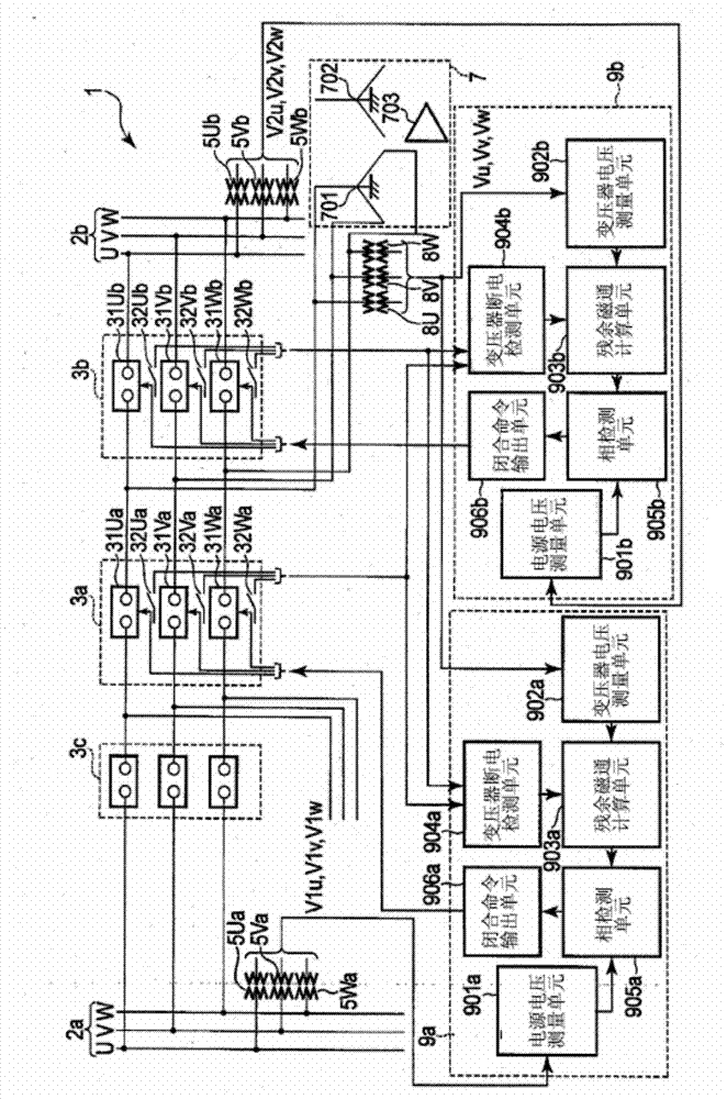
[0029] figure 1 The configuration of the magnetizing inrush current suppression system 1 according to the first embodiment of the present invention is illustrated. Components that are common to the figures below are denoted by common reference numerals, respectively. In the following, only the different parts in each figure will be described, and the description of the common parts will be omitted.

[0030] The magnetizing inrush suppression system 1 is used in a power system with a 1-1 / 2 (1.5) bus configuration.

[0031] The excitation inrush suppression system 1 includes: two power buses 2a and 2b; three circuit breakers 3a, 3b and 3c; two sets of power supply voltage detectors 5Ua, 5Va, 5Wa and 5Ub, 5Vb, 5Wb for three-phase detection; transformers 7; Transformer terminal voltage detectors 8U, 8V and 8W for three-phase detection; and two excitation inrush current suppression devices 9a and 9b.

[0032] The first power bus 2a and the second power bus 2b are buses of a powe...

no. 2 example

[0072] Figure 5 The configuration of an excitation inrush current suppression system 1A according to a second embodiment of the present invention is illustrated.

[0073] In the excitation inrush suppression system 1A, figure 1 The two magnetizing inrush suppressing devices 9a and 9b of the magnetizing inrush suppressing system 1 according to the first embodiment shown in , are replaced by two magnetizing inrush suppressing devices 9aA and 9bA, respectively. These two excitation inrush current suppressors 9aA and 9bA are connected through a transmission path for transmitting data. Other features of this configuration are the same as those of the magnetizing inrush suppression system 1 according to the first embodiment.

[0074] In the first excitation inrush current suppression device 9aA, figure 1 The residual magnetic flux calculation unit 903a, the transformer power failure detection unit 904a and the phase detection unit 905a of the first inrush current suppression dev...

no. 3 example

[0082] Figure 6 Shown is the configuration of a magnetizing inrush current suppression system 1B according to a third embodiment of the present invention.

[0083] In the excitation inrush suppression system 1B, figure 1 The two magnetizing inrush suppressing devices 9 a and 9 b of the magnetizing inrush suppressing system 1 according to the first embodiment shown in , are replaced by one magnetizing inrush suppressing device 9B. Other features of this configuration are the same as those of the magnetizing inrush suppression system 1 according to the first embodiment.

[0084]The excitation inrush current suppression device 9B includes two power supply voltage measurement units 901a and 901b, a transformer voltage measurement unit 902B, a residual magnetic flux calculation unit 903B, a transformer power-off detection unit 904B, two phase detection units 905a and 905b, and two closing command outputs Units 906a and 906b. The power supply voltage measurement unit 901a is the...


PUM


Abstract

According to an embodiment, when a transformer that is connected to a first power supply through a first breaker as well as to a second power supply through a second breaker is detected to be disconnected from the power supplies, a specific phase of the three phases of the first breaker is closed to suppress an excitation inrush current, based on calculated residual magnetic fluxes and a voltage of the first power supply, and thereafter, the remaining two phases are closed. Based on the calculated residual magnetic fluxes and a voltage of the second power supply, a specific phase of the three phases of the second breaker is closed to suppress an excitation inrush current, and thereafter, the remaining two phases are closed.

Description

technical field [0001] The embodiments described herein generally relate to a magnetizing inrush current suppression system (sometimes also called an inrush current suppression system), which is used to suppress the magnetizing inrush current generated when a transformer is energized. Background technique [0002] As we all know, when excitation is performed with no-load energization, since there is still magnetic flux around the transformer core, a large excitation inrush current will be formed. The magnetizing inrush current is several times larger than the rated load current of the transformer. If such a magnetizing inrush current with a large current value is formed, the system voltage will fluctuate. If the voltage fluctuates greatly, then this change is bound to affect consumers. [0003] According to a known method for suppressing magnetizing inrush currents, when the transformer is disconnected from the mains, the residual flux is calculated from the voltage signal...

Claims


Application Information

Patent Timeline
Patent Type & Authority Applications(China)
IPC IPC(8): H02H9/02
CPCH01H9/563H02H9/002
Inventor 丸山志郎斋藤实腰塚正三谷智彦
Owner KK TOSHIBA
Why Eureka
Try Eureka