Exciting inrush suppression system
A technology of excitation inrush current and suppression device, which is applied to emergency protection circuit devices, electrical components, electrical switches, etc. for limiting overcurrent/overvoltage, and can solve the problem of difficulty in excitation inrush current suppression.
- Summary
- Abstract
- Description
- Claims
- Application Information
AI Technical Summary
Problems solved by technology
Method used
Image
Examples
no. 1 example
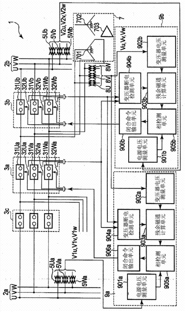
[0029] figure 1 The configuration of the magnetizing inrush current suppression system 1 according to the first embodiment of the present invention is illustrated. Components that are common to the figures below are denoted by common reference numerals, respectively. In the following, only the different parts in each figure will be described, and the description of the common parts will be omitted.
[0030] The magnetizing inrush suppression system 1 is used in a power system with a 1-1 / 2 (1.5) bus configuration.
[0031] The excitation inrush suppression system 1 includes: two power buses 2a and 2b; three circuit breakers 3a, 3b and 3c; two sets of power supply voltage detectors 5Ua, 5Va, 5Wa and 5Ub, 5Vb, 5Wb for three-phase detection; transformers 7; Transformer terminal voltage detectors 8U, 8V and 8W for three-phase detection; and two excitation inrush current suppression devices 9a and 9b.
[0032] The first power bus 2a and the second power bus 2b are buses of a powe...
no. 2 example
[0072] Figure 5 The configuration of an excitation inrush current suppression system 1A according to a second embodiment of the present invention is illustrated.
[0073] In the excitation inrush suppression system 1A, figure 1 The two magnetizing inrush suppressing devices 9a and 9b of the magnetizing inrush suppressing system 1 according to the first embodiment shown in , are replaced by two magnetizing inrush suppressing devices 9aA and 9bA, respectively. These two excitation inrush current suppressors 9aA and 9bA are connected through a transmission path for transmitting data. Other features of this configuration are the same as those of the magnetizing inrush suppression system 1 according to the first embodiment.
[0074] In the first excitation inrush current suppression device 9aA, figure 1 The residual magnetic flux calculation unit 903a, the transformer power failure detection unit 904a and the phase detection unit 905a of the first inrush current suppression dev...
no. 3 example
[0082] Figure 6 Shown is the configuration of a magnetizing inrush current suppression system 1B according to a third embodiment of the present invention.
[0083] In the excitation inrush suppression system 1B, figure 1 The two magnetizing inrush suppressing devices 9 a and 9 b of the magnetizing inrush suppressing system 1 according to the first embodiment shown in , are replaced by one magnetizing inrush suppressing device 9B. Other features of this configuration are the same as those of the magnetizing inrush suppression system 1 according to the first embodiment.
[0084]The excitation inrush current suppression device 9B includes two power supply voltage measurement units 901a and 901b, a transformer voltage measurement unit 902B, a residual magnetic flux calculation unit 903B, a transformer power-off detection unit 904B, two phase detection units 905a and 905b, and two closing command outputs Units 906a and 906b. The power supply voltage measurement unit 901a is the...
PUM
 Abstract
Description
Claims
Application Information
 - R&D
- Intellectual Property
- Life Sciences
- Materials
- Tech Scout
- Unparalleled Data Quality
- Higher Quality Content
- 60% Fewer Hallucinations
Browse by: Latest US Patents, China's latest patents, Technical Efficacy Thesaurus, Application Domain, Technology Topic, Popular Technical Reports.
© 2025 PatSnap. All rights reserved.Legal|Privacy policy|Modern Slavery Act Transparency Statement|Sitemap|About US| Contact US: help@patsnap.com


