Exciting inrush current suppression device

A technology of excitation inrush current and suppression device, which is applied in circuit devices, emergency protection circuit devices, emergency protection circuit devices for limiting overcurrent/overvoltage, etc., can solve the problem of difficulty in finding the intersection point of residual magnetic flux and constant magnetic flux, etc.

Active Publication Date: 2016-11-16
KK TOSHIBA
View PDF5 Cites 0 Cited by
  • Summary
  • Abstract
  • Description
  • Claims
  • Application Information

AI Technical Summary

Problems solved by technology

[0007] In the case of the residual magnetic flux having the AC component superimposed on the DC component in this way, it is difficult to obtain the intersection point of the residual magnetic flux and the permanent magnetic flux as described above.

Method used


Image

  • Exciting inrush current suppression device
  • Exciting inrush current suppression device
  • Exciting inrush current suppression device

Examples


Embodiment approach

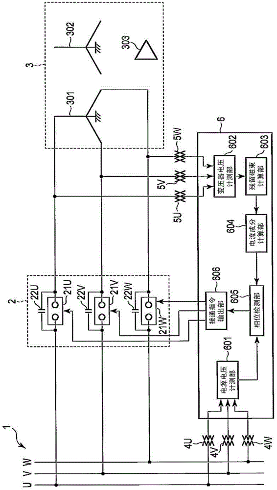
[0021] figure 1 It is a configuration diagram showing the configuration of a power system to which the excitation inrush current suppression device 6 according to the embodiment of the present invention is applied. In addition, the same reference numerals are assigned to the same parts in the subsequent drawings, and detailed description thereof will be omitted, and the different parts will be mainly described.

[0022] The power system according to this embodiment includes a power bus 1, a three-phase circuit breaker 2, a transformer 3, three-phase power supply voltage detectors 4U, 4V, and 4W, three-phase transformer terminal voltage detectors 5U, 5V, and 5W, and an excitation Surge suppression device 6.

[0023] The power supply bus 1 is a bus of an electric power system including a three-phase AC power supply composed of a U-phase, a V-phase, and a W-phase.

[0024] The primary side of the transformer 3 is connected to the power bus 1 via the circuit breaker 2 . The tra...


PUM


Abstract

According to one embodiment, a magnetizing inrush current suppressing device includes, a first closing unit closes the circuit-breaker at the notable phase by the first phase determined by the first-phase determination unit, a second-phase determination unit determines a second phase at which the notable phase detected by the notable phase detection unit from the three-phase AC voltage measured by the power-supply-side voltage measurement unit becomes a zero point after the first phase determined by the first-phase determination unit, and a second closing unit closes the circuit-breaker at two phases other than the notable phase by the second phase determined by the second-phase determination unit.

Description

technical field [0001] The present invention relates to a magnetizing inrush suppressing device for suppressing a magnetizing inrush generated when a transformer is turned on to a power supply. Background technique [0002] Generally, it is known that a large excitation inrush current flows when the power is turned on and no-load excitation is performed with residual magnetic flux in the transformer core. The magnitude of this magnetizing inrush current becomes several times the rated load current of the transformer. If a large inrush current flows in this way, the system voltage fluctuates. When this voltage fluctuation is large, it may affect the requester. [0003] As a method of suppressing this magnetizing inrush current, it is known that when connecting a directly grounded three-phase transformer with three single-phase circuit breakers, one of the arbitrary phases is first connected, and then the remaining two phases are connected. Methods of suppressing magnetizin...

Claims


Application Information

Patent Timeline
Patent Type & Authority Patents(China)
IPC IPC(8): H01H33/59H01H9/54H01H33/44H02H7/045H02J3/00
CPCH01H33/44H01H33/593H02H9/002H01H33/022H01H33/59
Inventor 腰塚正丸山志郎斋藤实前原宏之铃木浩二
Owner KK TOSHIBA
Why Eureka
Try Eureka