
rotary shaver head

A shaver and rotary technology, applied in metal processing and other directions, can solve the problems of inability to shave completely, affect the shaving effect, and difficulty, so as to improve shaving comfort, improve shaving effect, and avoid elastic aging Effect

Inactive Publication Date: 2017-02-22
WENZHOU QINGDONG HARDWARE PRODS
View PDF6 Cites 0 Cited by
  • Summary
  • Abstract
  • Description
  • Claims
  • Application Information

AI Technical Summary

Problems solved by technology

[0002] The razor heads currently on the market generally include a blade plastic frame and a net cover with blades installed. The blade plastic frame is arranged in the space formed by the ring body and the net cover. The blade plastic frame is equipped with an elastic mechanism. On the plastic frame, the blade relies on the elastic support provided by the blade plastic frame where it is located to push against the inner side of the net cover, but the force generated by the overall elastic rise of the blade plastic frame is generally not evenly distributed, and then the blades in each part are tightened to the side and top the net. The force of the cover is uneven, which easily affects the shaving effect
In addition, elastic parts are generally used for elastic support, and elastic parts are prone to aging and deformation, which not only brings a lot of inconvenience to the product in assembly and maintenance, but also increases the difficulty in the uniformity of force on the blade
And the existing rotary shaver head according to the user's feedback, when moving the shaver at a normal speed during the shaving process, there is a painful feeling of pulling the beard, especially when the beard is moved too fast and the beard is too long, the pain is more obvious
The reason is that it is caused by improper structure. The blade width of the moving knife (rigid component) of the rotary shaver head is shorter than that of the beard guide groove, and it is impossible to shave all the beard that enters the beard guide groove when shaving. The residual beard gets stuck in the groove and is pulled with the movement of the shaver, resulting in pain and discomfort, affecting the shaving effect

Method used


Image

  • rotary shaver head
  • rotary shaver head
  • rotary shaver head

Examples


Embodiment Construction

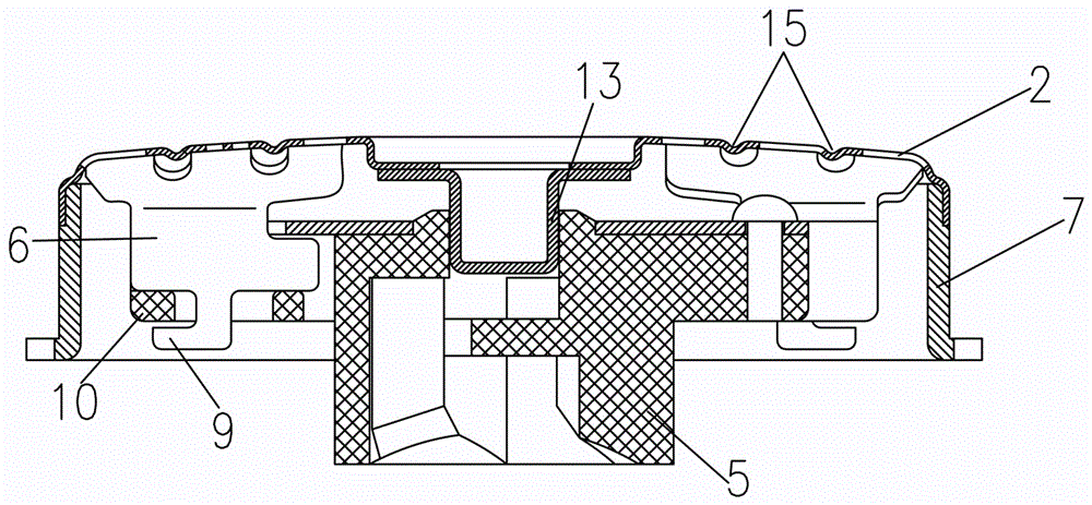
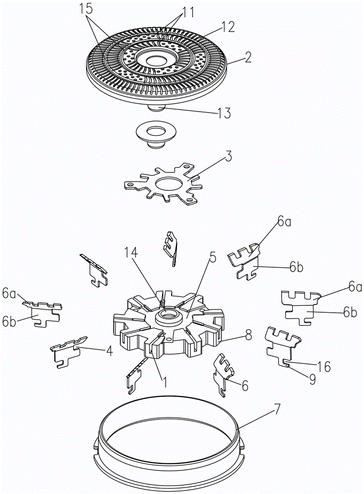
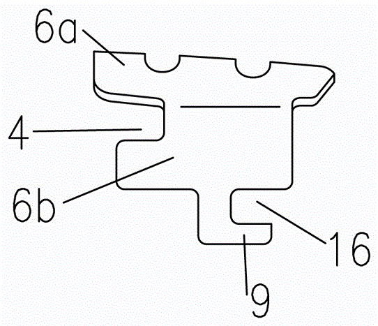
[0018] like figure 1 , figure 2 , image 3 , Figure 4 Shown, a kind of specific embodiment of rotary shaver cutter head of the present invention, a kind of rotary shaver cutter head, comprises net cover 2 and a blade plastic frame 5 that rotates relative to net cover 2, blade plastic frame 5 is provided with blade 6. Blade plastic frame 5 and three edge blades 6 are integrally installed in the space that net cover 2 surrounds and forms, and described blade plastic frame 5 comprises the center hole on the center of blade plastic frame 5, the annular evenly distributed blade mounting seat 8, described The central hole 14 cooperates with the fixed axis of rotation of the net cover 2, so that the plastic blade holder 5 rotates around the fixed axis of rotation 13. The blade mounting seat 8 is provided with a mounting groove 1 for mounting the blade 6 , the mounting groove 1 has an upward and outward outlet, and a block 10 is provided at the bottom of the mounting groove 1 . ...


PUM


Abstract

A rotary shaver tool bit comprises a mesh cover and a plastic blade frame rotating relative to the mesh cover. The plastic blade frame is provided with a blade and comprises a center hole and a blade installation base, wherein the center hole is formed in the center of the plastic blade frame and the blade installation base is evenly and annularly distributed. The blade is of an overall structure which is formed through one-shot stamping and comprises an upper-end cutting edge portion and a lower-end blade handle portion, the blade handle portion is vertically distributed, the cutting edge portion is bent and inclined towards on side relative to the blade handle portion, the middle of the inner side of the blade handle portion of the blade is provided with an inward concave portion, the middle of the lower end of the blade handle portion of the blade is provided with an L-shaped clamping foot, a clamping groove outside an opening is formed between the L-shaped clamping foot and the lower end of the blade handle portion, an cutting edge of the cutting edge portion of the blade is upward, the blade handle portion of the blade is inserted into an installation groove, and a steel gland and the plastic blade frame are in rivet connection and cover the bottom face of the inward concave portion of the blade. The rotary shaver tool bit is convenient to assemble and avoids the problems of elasticity aging of elastic elements and unevenness of elasticity, meanwhile, the requirement for the plastic blade frame is relative low, and cost is reduced.

Description

technical field [0001] The present invention relates to a shaver head. Background technique [0002] The razor heads currently on the market generally include a blade plastic frame and a net cover with blades installed. The blade plastic frame is arranged in the space formed by the ring body and the net cover. The blade plastic frame is equipped with an elastic mechanism. On the plastic frame, the blade relies on the elastic support provided by the blade plastic frame where it is located to push against the inner side of the net cover, but the force generated by the overall elastic rise of the blade plastic frame is generally not evenly distributed, and then the blades in each part are tightened to the side and top the net. The force of the cover is uneven, which easily affects the shaving effect. Furthermore, elastic parts are generally used for elastic support, and elastic parts are prone to aging and deformation, which not only brings a lot of inconvenience to the produc...

Claims


Application Information

Patent Timeline
Patent Type & Authority Patents(China)
IPC IPC(8): B26B19/14B26B19/38
Inventor 潘庆平
Owner WENZHOU QINGDONG HARDWARE PRODS
Learn More