
Zipper

A technology of zipper and chain cloth, applied in the field of zipper, can solve the problems of poor strength of chain teeth, poor strength of chain teeth 91, poor meshing strength, etc.

Inactive Publication Date: 2014-07-02
UNITECH ZIPPER & MACHINERY
View PDF5 Cites 4 Cited by
  • Summary
  • Abstract
  • Description
  • Claims
  • Application Information

AI Technical Summary

Problems solved by technology

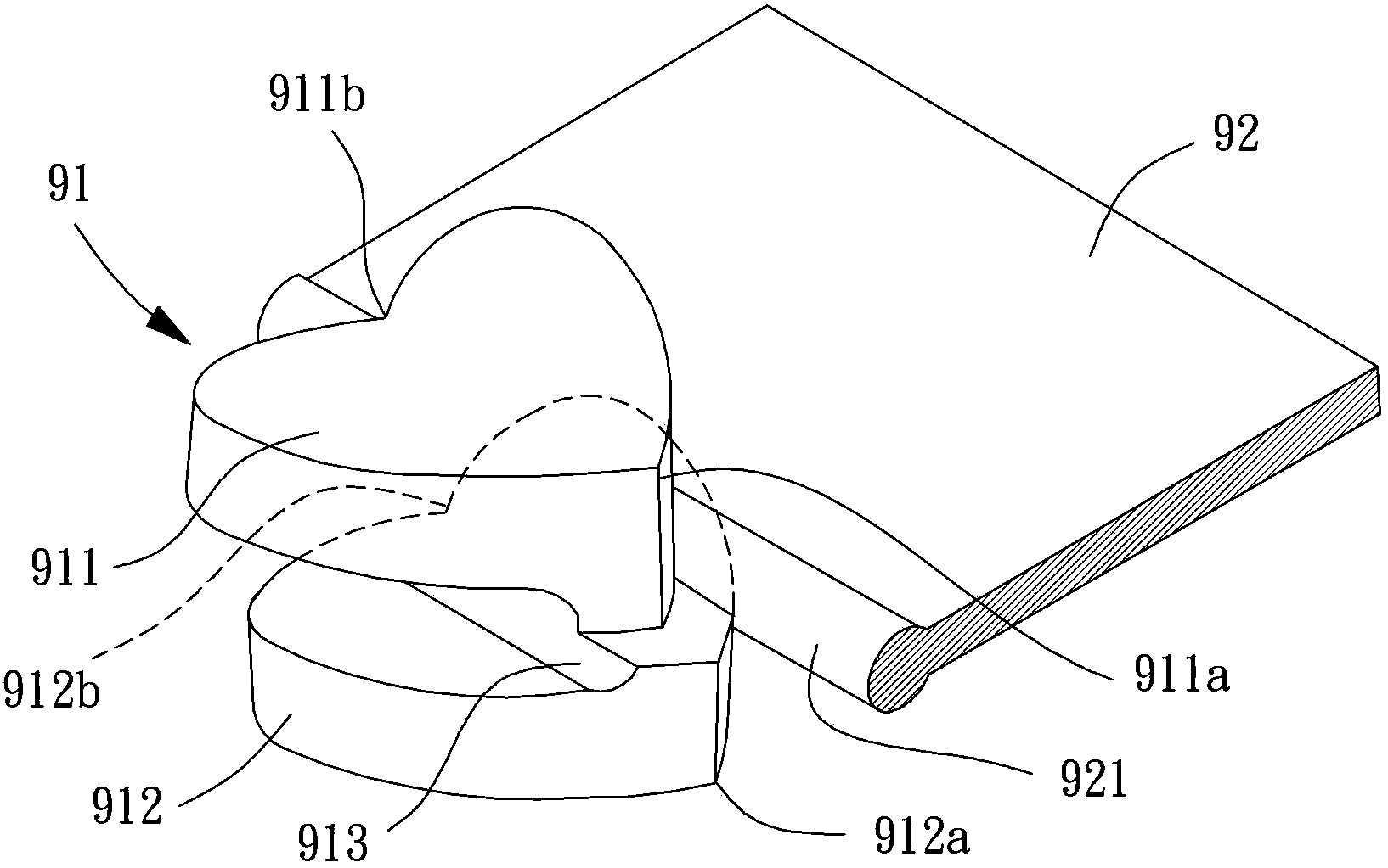
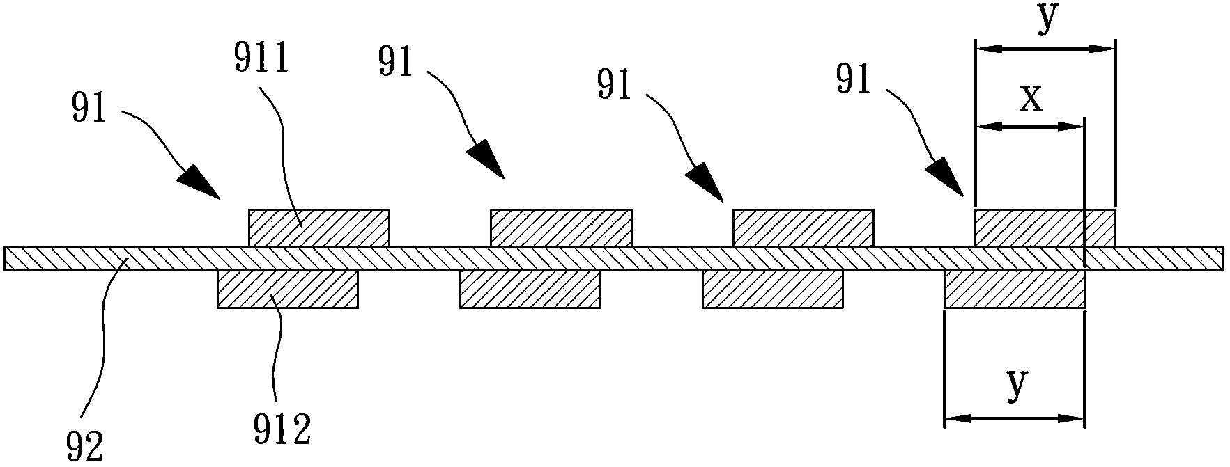
like image 3 As shown, it is a cross-sectional view of the state where the chain teeth 91 of the conventional slide fastener 9 are fixed on the chain cloth 92. The length of the chain cloth 92 should be the chain tooth length y of the surface part 911 or the back part 912 itself, but, because the surface part 911 and the back part 912 of the chain tooth 92 need to be misplaced, the surface part 911 and the back part The clamping length x of the chain cloth 92 clamped by the part 912 is shorter than the chain tooth length y, so the surface area of ​​the chain tooth 91 clamped by the chain cloth 92 is compared with the alignment of the surface part 911 and the back part 912. The situation at the time of installation is reduced, and there is a doubt that the strength of the sprocket 91 is poor
[0006] To sum up, the above-mentioned existing zipper 9 structure has problems such as poor meshing strength and poor strength of the chain teeth, and further improvement is urgently needed to enhance its practicability

Method used


Image

  • Zipper
  • Zipper
  • Zipper

Examples


Embodiment Construction

[0045] In order to make the above-mentioned and other objects, features and advantages of the present invention more comprehensible, the preferred embodiments of the present invention are specifically cited below, together with the accompanying drawings, as follows:

[0046] Please refer to Figure 4Shown is the zipper of the first embodiment of the present invention, which can be applied to all kinds of clothing such as coats, trousers or raincoats, and can also be applied to structures such as pockets, backpacks, handbags or suitcases of clothing. The zipper is composed of two chain cloths 1, several chain teeth 2 and a slider 3, the two chain cloths 1 are arranged opposite to each other, and the several chain teeth 2 are arranged in a staggered manner on the opposite side edges of the two chain cloths 1 . In addition, each chain tooth 2 of one chain cloth 1 can engage with two adjacent chain teeth 2 of the other chain cloth 1 . The slider 3 is respectively combined with t...


PUM


Abstract

Disclosed is a zipper. The zipper is used for solving the problem that an existing zipper is not firm in combination. The zipper comprises two zipper tapes and a plurality of zipper teeth. The two zipper tapes are respectively provided with a yarn core, and the two yarn cores are arranged opposite to each other. The zipper teeth are arranged on the yarn cores of the zipper tapes side by side in a staggered mode and respectively provided with a first meshing piece and a second meshing pipe. Each first meshing piece is provided with a convex meshing part and a concave meshing part at the two ends in the extension direction of the yarn cores respectively so that adjacent first meshing pieces can be meshed with each other through the convex meshing parts and the concave meshing parts. The zipper tapes are clamped by each second meshing piece and the corresponding first meshing piece jointly through a supporting part. The end, opposite to the corresponding supporting part, of each second meshing piece is provided with a buckling part. At least one concave clamping part is arranged between each buckling part and the corresponding supporting part so that adjacent second meshing pieces can be meshed with each other through the buckling parts and the clamping parts.

Description

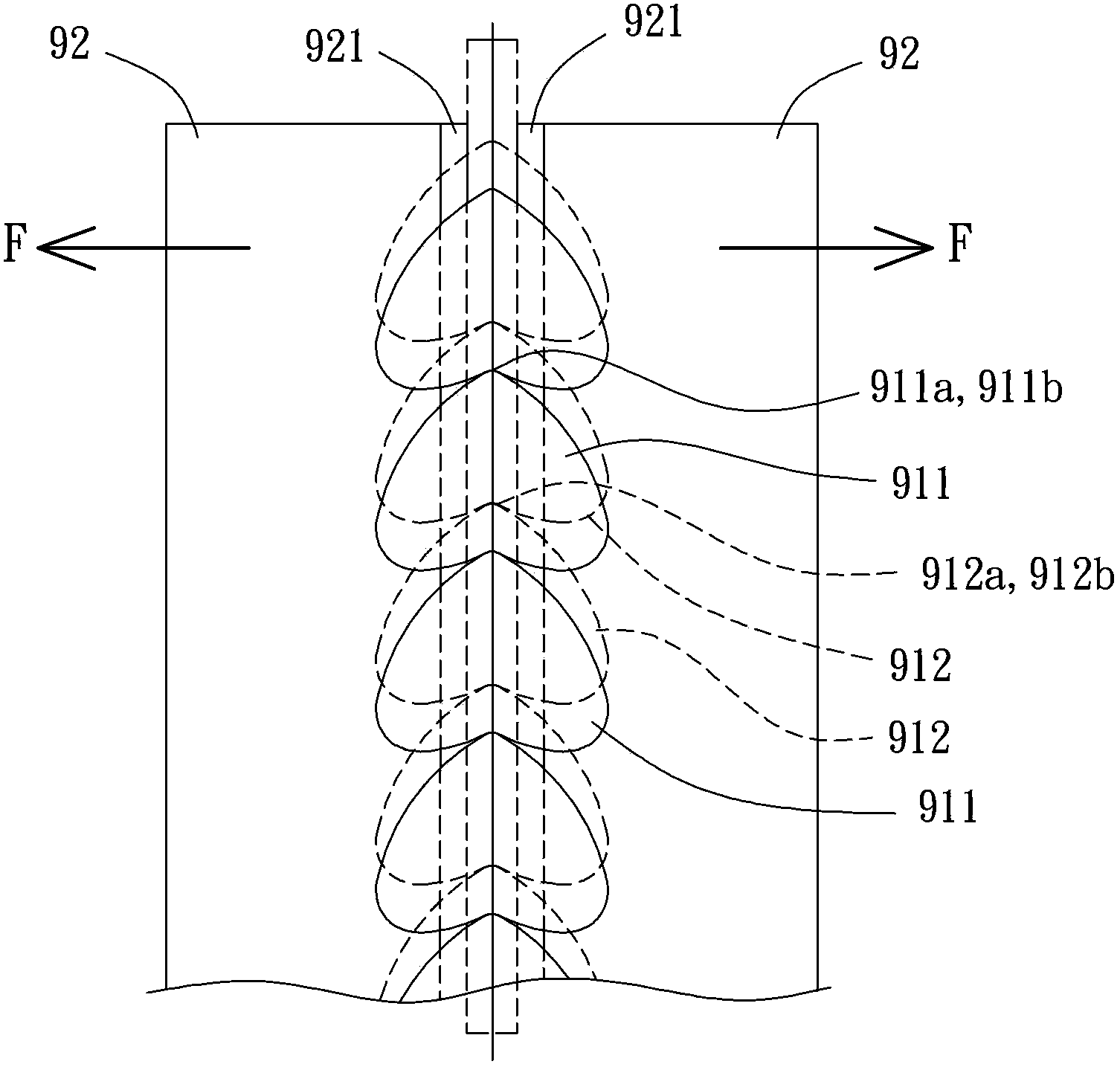
technical field [0001] The present invention relates to a zipper, especially a zipper with good engagement strength and beautiful appearance. Background technique [0002] Please refer to figure 1 , 2 As shown in and 3, the patent application for "zipper" published in Taiwan, China, discloses a kind of existing slide fastener 9, which is composed of several chain teeth 91 and two chain cloths 92, each of which chain teeth 91 includes a surface portion 911 , a back portion 912 and a groove 913, the two chain cloths 92 have opposite yarn cores 921. The plurality of chain teeth 91 are arranged on the opposite yarn cores 921 of the two chain cloths 92 , and the chain teeth 91 of each of the chain cloths 92 are misaligned. For the convenience of description, only one of the chain teeth 91 and one of the chain cloths 92 will be used for description below. The chain tooth 91 clamps the chain cloth 92 through the surface portion 911 and the back portion 912 to be fixed to the th...

Claims


Application Information

Patent Timeline
Patent Type & Authority Applications(China)
IPC IPC(8): A44B19/00A44B19/26
Inventor 郑荣元
Owner UNITECH ZIPPER & MACHINERY
Learn More