Automatic demolding type replaceable injection mold

A technology of injection molds and molds, which is applied in the field of mold replaceable and automatic mold release injection molds, can solve the problems of inability to use various product shapes, complex injection mold design, inconvenient use, etc., to achieve easy replacement, long service life, The effect of protecting the putter

Inactive Publication Date: 2014-07-02
昆山钧鼎精密模具有限公司
View PDF4 Cites 1 Cited by
  • Summary
  • Abstract
  • Description
  • Claims
  • Application Information

AI Technical Summary

Problems solved by technology

[0004] For example, CN202623194 discloses a demoulding structure for injection molds, which is driven by a hydraulic cylinder, has a compact structure, stable and reliable mechanical action, and is easy to process, but the demoulding of the injection mold is realized through an external independent injection mold demoulding structure, and the cost increases. Inconvenient to use
[0005] CN203496238 discloses an injection mold that is easy to demould. The push tube in the cavity shell is changed to be pushed by the push plate. The injection molding rate is low, and the cost is low, and there are fewer obstacles during demoulding, which is conducive to smooth demoulding. However, the design of the injection mold is complicated. It is only possible to use a variety of product shapes by changing the push tube to the push plate.

Method used


Image

  • Automatic demolding type replaceable injection mold

Examples


Embodiment Construction

[0025] The present invention will be further explained below in conjunction with the drawings.

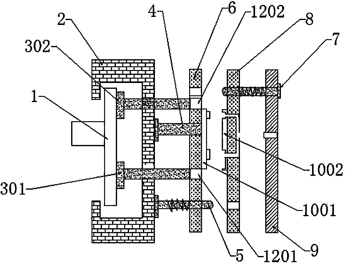
[0026] Such as figure 1 As shown, the mold can be replaced with an automatic demolding injection mold, including a demolding guide rod support 1, a thrust seat 2, a first demolding rod 301, a second demolding rod 302, a push rod 4, a first limit rod 5, The first mold seat 6, the second limiting rod 7, the second mold seat 8 and the gate cover 9.

[0027] The sprue sleeve 9 is provided with a sprue sleeve hole, and the second mold base 8 is provided with a flow glue inlet hole opposite to the sprue sleeve hole.

[0028] The thrust surface of the demolding guide rod support 1 and the thrust surface of the thrust seat 2 are arranged in parallel, the first mold seat 6 is provided with a first demolding through hole 1201, a second demolding through hole 1202, and a first demolding rod 301 , One end of the second demolding rod 302 is fixedly connected to the demolding guide rod support 1, and...


PUM


Abstract

The invention discloses an automatic demolding type replaceable plastic injection mold which comprises a demolding guide rod support (1), a thrust block (2), a first demolding rod (301), a second demolding rod (302), a push rod (4), a first limiting rod (5), a first mold holder (6), a second limiting rod (7), a second mold holder (8), a sprue bush sleeve (9), a first mold (1001) and a second mold (1002), wherein two ends of the push rod (4) are fixedly connected with the thrust block (2) and the first mold holder (6) respectively; the first mold (1001) and the second mold (1002) are respectively arranged on the first mold holder (6) and the second mold holder (8) through screws; a first demolding through hole (1201) and a second demolding through hole (1202) are respectively formed in the upper edge and the lower edge of the first mold (1001). The structure can be suitable for different injection molds, and the injection mold is convenient to replace. With the double limiting rods, the injection mold is precisely positioned and is prevented from moving.

Description

Technical field [0001] The invention relates to the field of injection molds, in particular to an injection mold with replaceable molds and automatic demolding. Background technique [0002] In the prior art, due to the shape of the injection molded product, the injection mold is only used for one product. When the product shape is changed, the injection mold needs to be redesigned, reinstalled, and it is troublesome to disassemble and assemble. One product corresponds to a set of mold components. It even corresponds to a complete set of injection molding machines, which is costly. [0003] At the same time, in the prior art, the injection mold that is automatically demolded is demolded by ejection, that is, the demolding rod is directly used as a mold to eject and demold. [0004] For example, CN202623194 discloses an injection mold demolding structure, which is driven by a hydraulic cylinder, has a compact structure, stable and reliable mechanical action, and is easy to process. H...

Claims


Application Information

Patent Timeline
Patent Type & Authority Applications(China)
IPC IPC(8): B29C45/40B29C45/27
CPCB29C45/1742B29C45/27B29C45/4005
Inventor 王枫
Owner 昆山钧鼎精密模具有限公司
Why Eureka
Try Eureka