Device and method for manufacturing plaster mold

A gypsum mold and mold sleeve technology, applied in mold fixtures, molds, manufacturing tools, etc., can solve problems such as deformation of ceramic products, and achieve the effect of reducing dosage and improving production efficiency

Inactive Publication Date: 2016-05-25
湖北朗驰新型材料有限公司
View PDF7 Cites 6 Cited by
  • Summary
  • Abstract
  • Description
  • Claims
  • Application Information

AI Technical Summary

Problems solved by technology

However, silicon carbide ceramic burner sleeves with a diameter higher than 800mm are likely to cause

Method used


Image

  • Device and method for manufacturing plaster mold
  • Device and method for manufacturing plaster mold
  • Device and method for manufacturing plaster mold

Examples


Embodiment 1

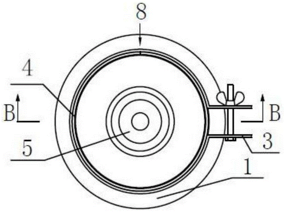
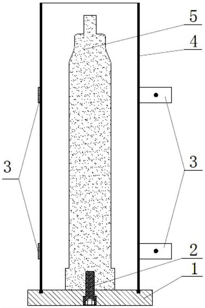
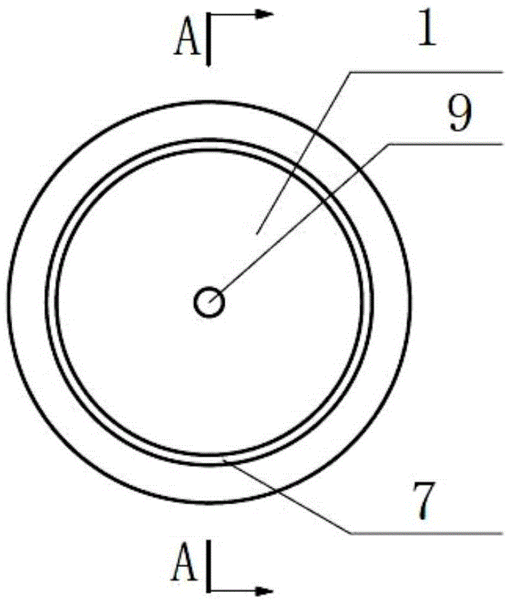
[0041] Such as Figure 1 to Figure 7 As shown, it is a device for making plaster molds provided by the embodiment of the present invention, which includes a mold core 5, a mold sleeve 4 sleeved outside the mold core 5, a chassis 1 and a clamping device. There is a molding cavity 31 between the mold cover 4 and the mold core 5 (such as Figure 9 shown). The bottoms of the mold casing 4 and the mold core 5 are all fixed on the chassis 1 . Die cover 4 is provided with a longitudinal opening 8 from the axial direction of mold core (such as Image 6 shown). The clamping device is used for clamping the mold cover 4. Both the inner surface of the mold casing 4 and the outer surface of the mold core 5 are provided with a release agent layer.

[0042] The mold core 5 includes a main body portion and a discharge port forming portion from bottom to top along its axial direction, and the width of the main body portion is greater than that of the discharge port forming portion. The c...

Embodiment 2

[0054] This embodiment is roughly the same as Embodiment 1, the difference is:

[0055] 1) if Figure 10 As shown, the total height of the mold core 19 of this embodiment is 800mm, and its main body includes a first mold core 20, a second mold core 21, and a third mold core 22 connected in sequence from bottom to top along its axial direction. , and the pulp opening forming part 23. The diameter of the first mold core 20 is d 7 . The diameter of the third mold core 22 is d 9 . The diameter of the pulp opening forming part 23 is d 10 . d 7 、d 9 、d 10 is a certain value and d 7 >d 9 >d 1 . The diameter d of the second mold core 21 8 gradually decreases from bottom to top. The maximum diameter of the second core 21 and the diameter of the first core d 7 Same, the minimum diameter of the second mold core 21 is the same as the third mold core diameter d 9 same. The outer wall 20 of the first mold core is provided with external threads.

[0056] 2) According to th...

Embodiment 3

[0059] This embodiment is roughly the same as Embodiment 1, the difference is:

[0060] 1) if Figure 11 As shown, the total height of the mold core 24 of this embodiment is 1100 mm, and its main body includes a first mold core 25, a second mold core 26, and a third mold core 27 connected in sequence from bottom to top along its axial direction. , the fourth mold core 28 and the slurry opening forming part 29 . The diameter of the first mold core 25 is d 11 . The diameter of the second mold core 26 is d 12 . The diameter of the fourth mold core 28 is d 14 . The diameter of the pulp opening forming part 2329 is d 15 . d 11 、d 12 、d 14 、d 15 is a certain value and d 11 >d 12 >d 14 >d 15 . The diameter d of the third mold core 27 13 gradually decreases from bottom to top. The maximum diameter of the third core 27 and the second core diameter d 12 Same, the minimum diameter of the third mold core 27 is the same as the fourth mold core diameter d 14 same. The ...


PUM


Abstract

The invention discloses a device and method for manufacturing a plaster mold. The device comprises a mold core, a mold sleeve sleeving the mold core, a chassis and a banding device, wherein a molding cavity is formed between the mold sleeve and the mold core, both the bottom of the mold sleeve and the bottom of the mold core are fixed on the chassis, a longitudinal opening is formed in the mold sleeve from the axial direction of the mold core, and the banding device is used for banding the mold sleeve. The method sequentially comprises the steps of smearing a mold releasing agent, assembling the device for manufacturing the plaster mold, blocking up periphery gaps of the device for manufacturing the plaster mold, preparing calcium plaster, and molding the plaster mold. By using the device and the method, the manufacturing efficiency of the plaster mold can be increased, the use level of plaster powder can be lowered, and the manufactured plaster mold can be used for greatly increasing the grouting molding efficiency of ceramics and reducing subsequent workloads of production of the ceramics.

Description

technical field [0001] The invention relates to a device and a manufacturing method for making plaster molds, which are suitable for the field of grouting molding of ceramics. Background technique [0002] In the ceramic production industry, plaster molds are the most widely used traditional grouting molding molds, such as sanitary ceramics, daily ceramics, special ceramics with complex shapes and structures, and other types of ceramics. Compared with grouting molds made of other materials, plaster molds have the advantages of rich sources of raw materials, low price, simple manufacturing process, high water absorption, and good dimensional stability. [0003] For the grouting molded ceramic products whose wall thickness is less than 10mm, the cross section is circular, and the diameter gradually decreases from one end to the other end in the length direction, the gypsum mold used in its production is generally made into a split gypsum mold with at least two parts. When mol...

Claims


Application Information

Patent Timeline
IPC IPC(8): B28B7/16B28B7/00B28B1/14
CPCB28B1/14B28B7/0014B28B7/0029B28B7/16
Inventor 何婵曾宪刚
Owner 湖北朗驰新型材料有限公司
Why Eureka
Try Eureka