Fence structure applicable to complicated topographic structures
A technology for complex terrain and fences, applied in the direction of fences, building types, buildings, etc., can solve problems such as difficult adaptation and inconvenient installation, and achieve the effect of improving installation efficiency
- Summary
- Abstract
- Description
- Claims
- Application Information
AI Technical Summary
Problems solved by technology
Method used
Image
Examples
Embodiment 1
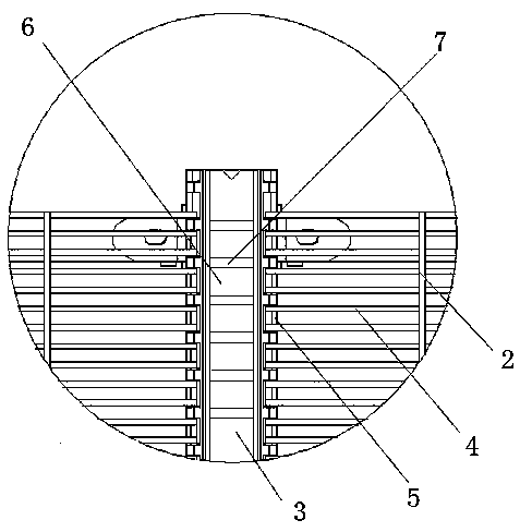
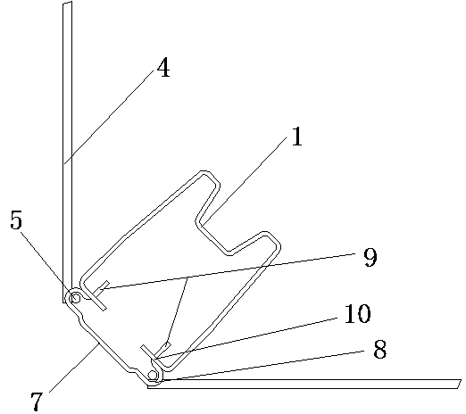
[0027] Such as figure 1 and figure 2 Shown is a fence structure suitable for complex terrain structures, which includes a fence column 1, a fence mesh 2, and a fence pressure plate 3; the fence mesh 2 is composed of a plurality of horizontal fences 4 and vertical fences The fence column 1 and the fence mesh 2 are connected through a fence pressure plate 3 . The fence pressing plate 3 is composed of a plurality of connecting groove blocks evenly arranged along the extending direction of the fence column 1, and the adjacent connecting groove blocks are connected by a connecting plate 6, and the connecting plate 6 between each pair of adjacent connecting groove blocks , the length in the extension direction of the fence column 1 is greater than the diameter of the rail 4 in the fence mesh; each connecting groove block includes two fixed grooves, and a fixed plate 7 connecting between the fixed grooves .
[0028] As an improvement of the present invention, the fixed grooves in...
Embodiment 2
[0033] At least one splicing device capable of splicing in the horizontal direction is provided in the connecting groove block.
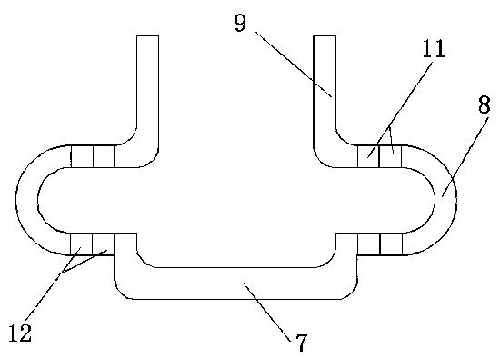
[0034] As an improvement of the present invention, such as image 3 As shown, between the C-shaped semicircular groove 8 and the pressure plate teeth 9, and between the C-shaped semicircular groove 8 and the fixed plate 7, a plurality of first splicing plates 11 and second splicing plates parallel to the plane where the fixed plate is located are respectively provided. The splicing plate 12; the first splicing plate 11, the second splicing plate 12, the C-shaped semicircular groove 8, the pressing plate teeth 9 and the fixing plate 7 are all provided on the intersecting end faces of the first splicing plate 11, the second splicing plate 12, the buckles corresponding to the positions and sizes Connect with the card slot. With the above-mentioned design, the splicing structure of the first splicing plate, the second splicing plate, and other parts in...
Embodiment 3
[0039] As another improvement of the present invention, such as Figure 4 As shown, the buckle is composed of a columnar button body 14 and a spherical button end 15 arranged at the end of the columnar button body 14. The diameter of the spherical button end 15 ranges from 5 / 4 to the diameter of the bottom surface of the columnar button body 14. 2 / 3; the draw-in groove is made of a cylindrical groove body 16 with the same diameter as the spherical buckle end, and the inside of the cylindrical groove body 16 is provided with a ring-shaped bracket 17, and its starting end is fixed in the inside of the cylindrical groove body 16, and from the end to the The cylindrical groove body 16 extends in the axial direction; the depth of the cylindrical groove body 16 is the same as the buckle height; the terminal diameter of the ring bracket 17 is the same as that of the cylindrical buckle body, and it is located where the buckle fully extends into the cylindrical groove body 16 , the int...
PUM
 Abstract
Description
Claims
Application Information
 - R&D
- Intellectual Property
- Life Sciences
- Materials
- Tech Scout
- Unparalleled Data Quality
- Higher Quality Content
- 60% Fewer Hallucinations
Browse by: Latest US Patents, China's latest patents, Technical Efficacy Thesaurus, Application Domain, Technology Topic, Popular Technical Reports.
© 2025 PatSnap. All rights reserved.Legal|Privacy policy|Modern Slavery Act Transparency Statement|Sitemap|About US| Contact US: help@patsnap.com


