

Safety instrument system and method for permitting PST
A technology of safety instrumented system and start command, which is applied in the field of safety instrumented system, can solve the problem of high cost and achieve the effect of suppressing bad influence
- Summary
- Abstract
- Description
- Claims
- Application Information
AI Technical Summary
Problems solved by technology
Method used
Image

Examples
no. 1 approach ]
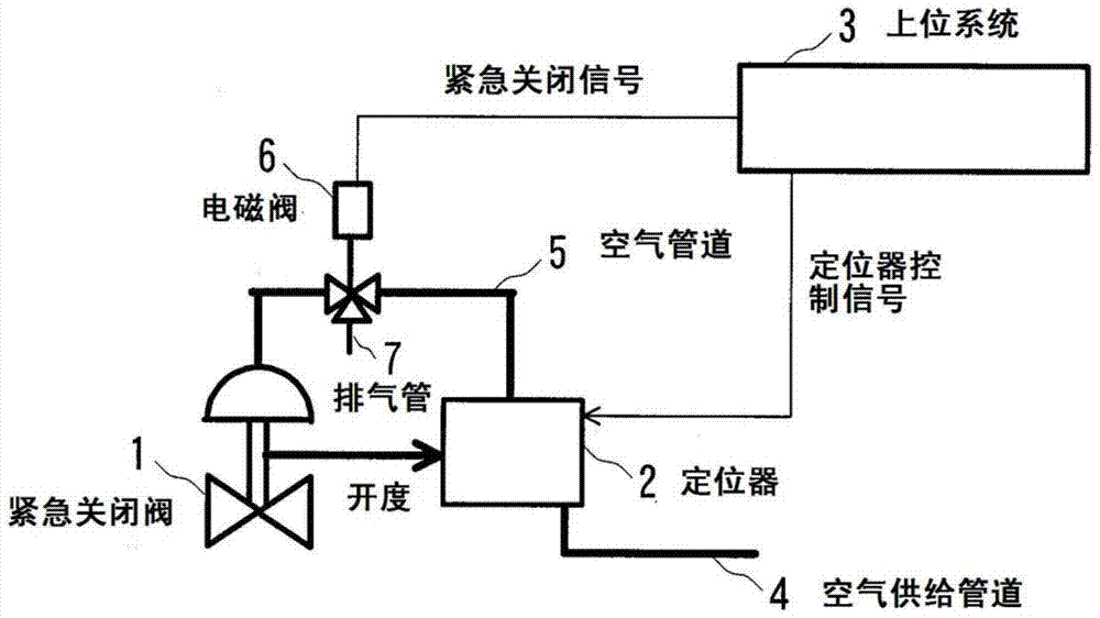
[0041] Hereinafter, embodiments of the present invention will be described with reference to the drawings. figure 1 It is a block diagram showing the configuration of the safety instrumented system according to the first embodiment of the present invention.
[0042] The emergency shut-off valve 1 set in the pipeline of the process equipment to prevent accidents of the process equipment in the future is driven by air pressure. The positioner 2 that controls the opening of the emergency shut-off valve 1 receives a positioner control signal from the host system 3 that manages the maintenance of each field device of the process equipment, and uses the air supply from the air supply according to the opening indication value shown by the positioner control signal. The air in the pipe 4 supplies the required operator air pressure to the emergency shut-off valve 1. Operator air pressure from positioner 2 is supplied to emergency shut-off valve 1 through air duct 5 . In addition, the...
no. 2 approach ]
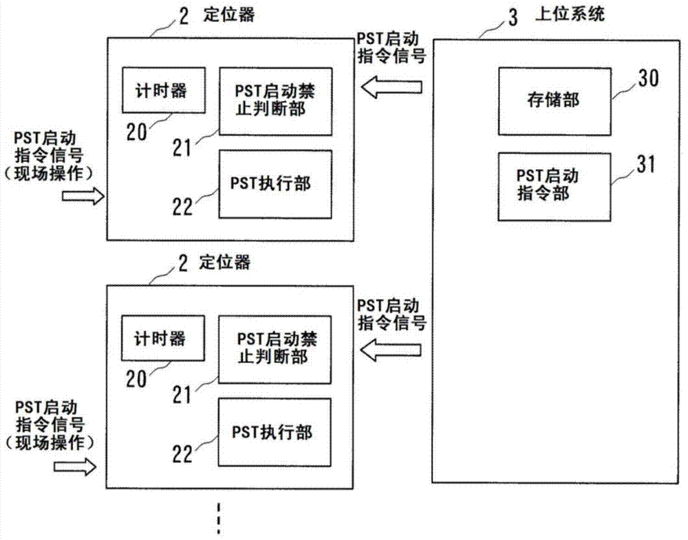
[0054] Next, a second embodiment of the present invention will be described. Figure 4 It is a block diagram showing the structure of the positioner 2 and the host system 3 in this embodiment. In this embodiment, since the overall structure of the safety instrumented system is also the same as that of the first embodiment, using figure 1 symbols are explained. In the first embodiment, the locator 2 manages the PST activation period, and individually judges whether the PST can be activated. On the other hand, in the present embodiment, the host system 3 manages the PST activation cycle of the plurality of emergency shut-off valves 1, and judges whether or not the PST activation is possible.
[0055] The host system 3 has a storage unit 30, a PST start instruction unit 31, a PST start prohibition determination unit 32 for judging the prohibition / permission of PST start-up of each emergency shut-off valve 1, and a timer 33 for measuring The time elapsed after the PST is comple...
no. 3 approach ]
[0064] Next, a third embodiment of the present invention will be described. Figure 6 It is a block diagram showing the structure of the positioner 2 and the host system 3 in this embodiment. In this embodiment, since the overall structure of the safety instrumented system is the same as that of the first embodiment, using figure 1 symbols are explained. In the second embodiment, the PST performed by the command from the higher-level system 3 is periodically executed regardless of the PST performed by the command from the operation panel on site. On the other hand, this embodiment combines the PST performed by the command from the host system 3 and the PST performed by the command from the operation panel on site.
[0065] When the originally scheduled PST is activated by the PST activation command signal of the host system 3 without a sufficient time interval after completion of the PST performed by the on-site operation, the PST becomes an unnecessary PST that may not be a...
PUM
 Abstract
Description
Claims
Application Information