
Plastic joint cutting machine

A cutting machine and plastic technology, applied in metal processing and other directions, can solve the problems of time-consuming and labor-intensive, and achieve the effects of easy operation, low machine cost and labor cost

Inactive Publication Date: 2014-07-09
张国勇
View PDF0 Cites 0 Cited by
  • Summary
  • Abstract
  • Description
  • Claims
  • Application Information

AI Technical Summary

Problems solved by technology

[0002] In the injection molding industry, after the injection molded part is removed from the mold, there is usually a section of the remaining joint of the injection gate. The simple operation is to use manual removal, which is time-consuming and laborious.

Method used


Image

  • Plastic joint cutting machine

Examples


Embodiment Construction

[0011] Below in conjunction with accompanying drawing, the present invention will be described in further detail:

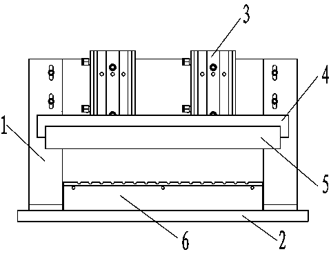
[0012] A plastic joint cutting machine, including a bracket 1 and a base 2, wherein the bracket 1 is installed on the base 2, and a cylinder 3 is installed on the bracket 1, and the piston on the cylinder 3 passes through a slide rail 4 and a cutter 5 Connected, the base 2 is equipped with a lower pad 6 .

[0013] Further, the number of the cylinders 3 is at least two. Multiple cylinders are fixed on the bracket evenly, and act on the slide rail to make the force more uniform, and can effectively and neatly cut the joint.

[0014] Further, the lower cushion block 6 is arranged directly below the cutter 5, and the joint is cut off by the pressing action of the cutter 5 and the lower cushion block 6 when the cutter 5 is pressed down.

[0015] When the present invention is actually used, the injection molded part to be cut is placed on the lower pad 6, the cylinde...


PUM


Abstract

The invention discloses a plastic joint cutting machine. The plastic joint cutting machine comprises a support and a base, wherein the support is mounted on the base, a cylinder is mounted on a support, a piston of the cylinder is connected to a cutting tool by virtue of a sliding rail, and a lower cushion block is mounted on the base. The plastic joint cutting machine has the beneficial effects that the simple plastic joint cutting machine suitable for small-scale production is provided, and firstly, the machine is low in cost and convenient to operate so that a worker can operate the machine without being trained, and secondly, the machine is capable of cutting a batch of joints, and therefore, the working efficiency is improved and the manual cost is reduced.

Description

technical field [0001] The invention relates to a joint cutting machine, in particular to a simple plastic joint cutting machine. Background technique [0002] In the injection molding industry, after the injection molded part is removed from the mold, there is usually a section of joint left over from the injection gate. The simple operation is to use manual removal, which is time-consuming and laborious. The invention provides a simple plastic joint cutting machine. Contents of the invention [0003] In view of the above problems, the present invention proposes a plastic joint cutting machine, including a bracket and a base, wherein the bracket is installed on the base, and a cylinder is installed on the bracket, and the piston on the cylinder is connected to the cutter through a slide rail. A lower pad is installed on the base. [0004] Further, the number of the cylinders is at least two. Multiple cylinders are fixed on the bracket evenly, and act on the slide rail ...

Claims


Application Information

Patent Timeline
IPC IPC(8): B26D1/08B29C45/38
Inventor 张国勇
Owner 张国勇
Learn More