
Radio-frequency (RF) power distribution device

A technology of radio frequency power and distribution device, which is applied in the direction of connection devices, electrical components, circuits, etc., can solve problems such as the complexity of multi-energy feed-in points, achieve uniform plasma distribution, save machine costs, and save quantity.

Inactive Publication Date: 2013-03-13
ASIATREE TECH
View PDF3 Cites 0 Cited by
  • Summary
  • Abstract
  • Description
  • Claims
  • Application Information

AI Technical Summary

Problems solved by technology

However, the multi-energy feeding point method disclosed in this patent is too complicated
However, in response to industry trends, it is inevitable to process large-area coated substrates with multiple feed-in points

Method used


Image

  • Radio-frequency (RF) power distribution device
  • Radio-frequency (RF) power distribution device
  • Radio-frequency (RF) power distribution device

Examples


Embodiment Construction

[0044] Although the present invention may be embodied in different forms, the drawings and description below are preferred embodiments of the present invention, and please understand that the disclosure herein is considered to be an example of the present invention and is not intended to It is intended to limit the invention to the drawings and / or the specific embodiments described.

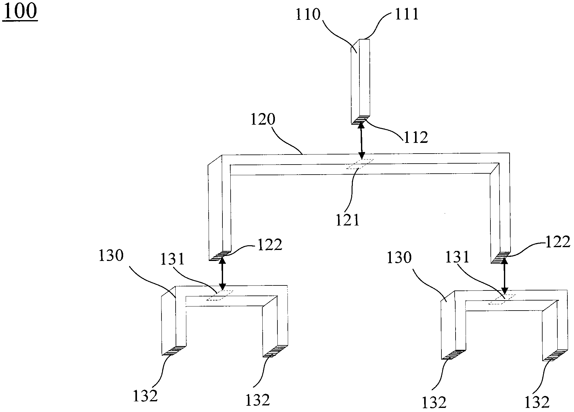
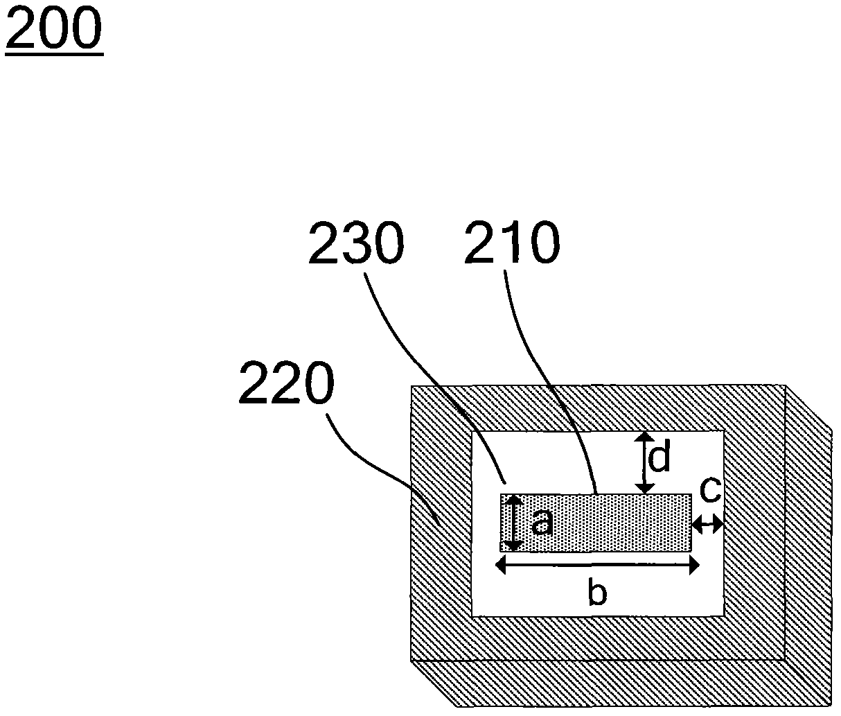
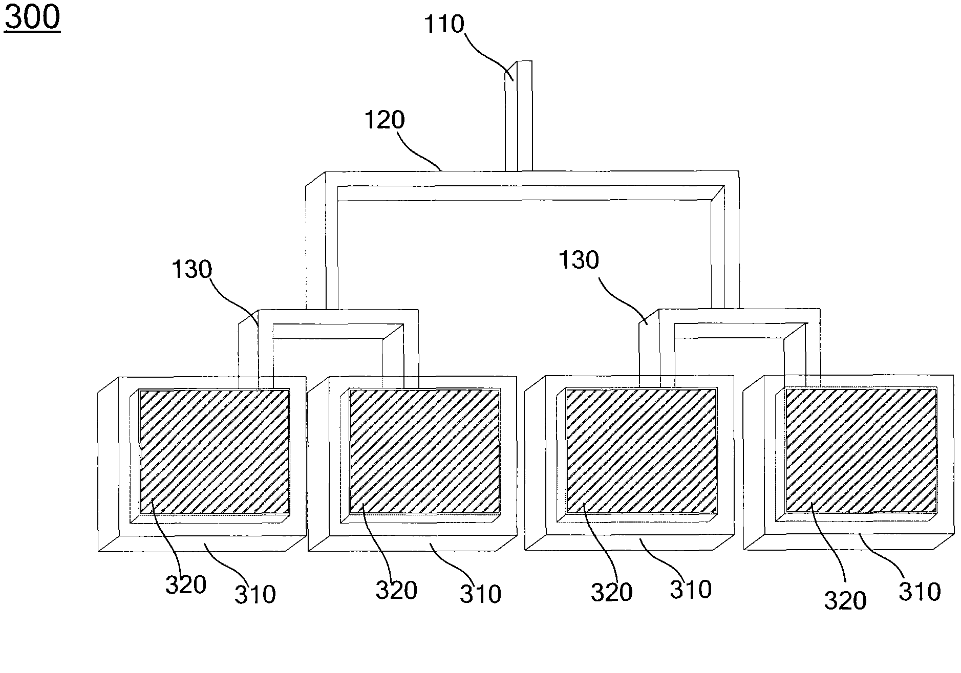
[0045] now please refer to figure 1 , is a schematic diagram of the first embodiment of the present invention, which includes: a power input unit 110 , a first power distribution unit 120 and a plurality of second power distribution units 130 . The power input unit 110 has a first input terminal 111 and a first output terminal 112 . The first input terminal 111 is used for inputting radio frequency power, and is conventionally used for connecting a radio frequency power generator (RF power generator). The radio frequency power is output to the first power distribution unit 120 through the first...


PUM


Abstract

The invention discloses an RF power distribution device. A two-stage powder distribution unit is adopted, the RF power can be equally split into four pieces through coaxial transmission lines with specific sizes and impedance, thereby, the RF power input into the device can be effectively distributed and output, and the device can be applied to a plasma apparatus.

Description

technical field [0001] The present invention relates to a radio frequency power distribution device, and in particular to a method of using a coaxial transmission line capable of carrying high power, which can be used in a plasma apparatus (plasma apparatus), saves the number of radio frequency power generators, and produces a large area and Uniform plasma distribution. Background technique [0002] In today's semiconductor process technologies, such as fabs or chip-type solar plants, plasma-enhanced chemical vapor deposition (Plasma enhance chemical vapor deposition, PECVD) systems can achieve very high Efficient thin film deposition. [0003] In addition, the traditional microcrystalline silicon thin-film solar cell process method is to pass a large amount of hydrogen and silane into the plasma-enhanced chemical vapor deposition process for dilution, and then form a microcrystalline silicon thin film through the reaction to improve the silicon thin-film solar cell. Vario...

Claims


Application Information

Patent Timeline
IPC IPC(8): H01P5/12
Inventor 李炳寰杨主见黄维致黄俊凯叶昌鑫
Owner ASIATREE TECH
Learn More