
Adjustable device for temporarily stabilizing the material to be cut on the cutting table

A cutting material, adjustable technology, applied in fur cutting, application, leather punching/punching/cutting, etc., can solve problems such as increased production cost

Active Publication Date: 2017-09-01
原子股份公司
View PDF4 Cites 0 Cited by
  • Summary
  • Abstract
  • Description
  • Claims
  • Application Information

AI Technical Summary

Problems solved by technology

In these cases, the material is not always recoverable and the damaged part has to be discarded, the overall production cost will be greatly increased

Method used


Image

  • Adjustable device for temporarily stabilizing the material to be cut on the cutting table
  • Adjustable device for temporarily stabilizing the material to be cut on the cutting table
  • Adjustable device for temporarily stabilizing the material to be cut on the cutting table

Examples


Embodiment Construction

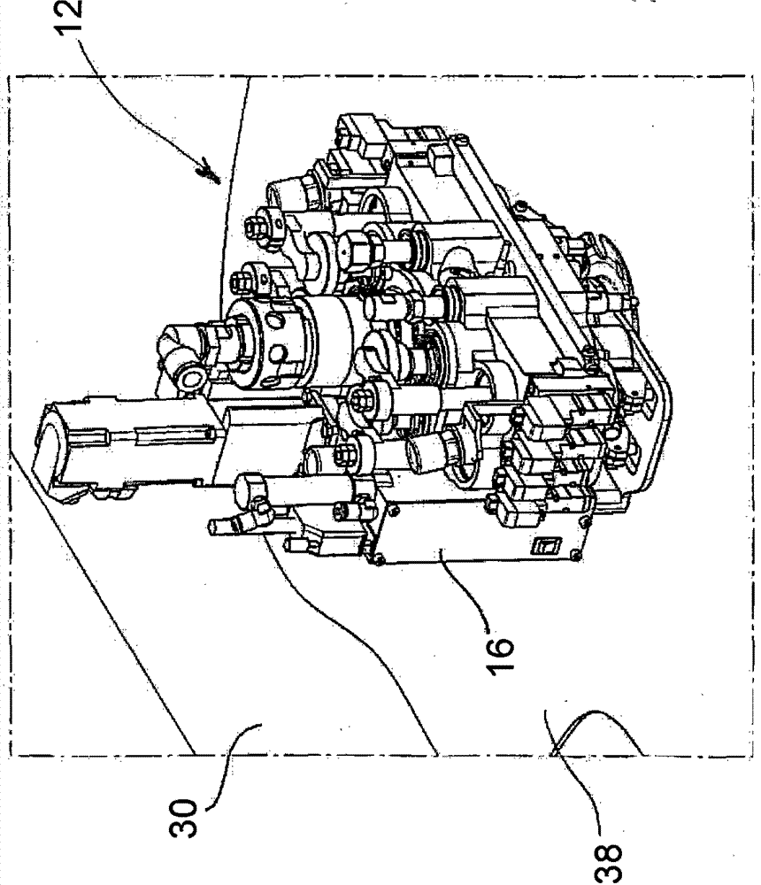
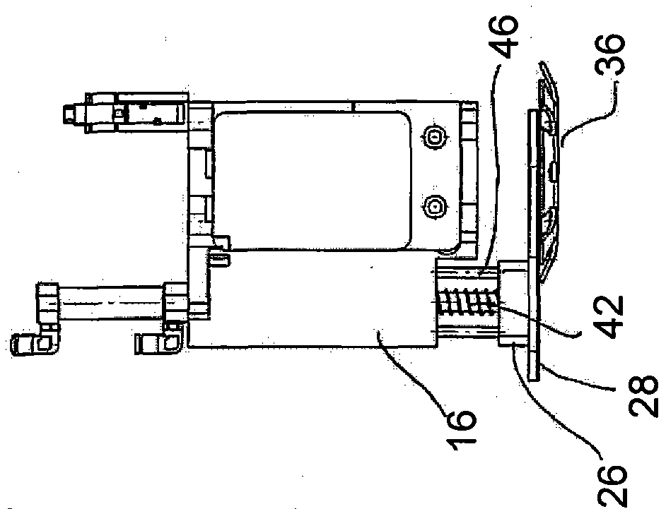
[0022] first reference figure 1 with Image 6 , an adjustable device for temporarily stabilizing the material to be cut on the cutting table Image 6 The reference number 10 in indicates that the device is combined with a cutting unit known per se, which is in figure 1 Indicated by reference numeral 12. The device 10 comprises a frame 14 carrying a pneumatic cylinder 18 or equivalent within a housing 16, in Figure 7 with Figure 8 are shown in more detail. Said pneumatic cylinder is combined with a double-acting solenoid valve 20 which produces movement and causes the cylinder rod 22 to rise and fall. The cylinder rod 22 is integral with a shaft 24, the lower end of which (lower end) engages a substantially annular body 26; the latter constitutes a support for a plate 28 projecting from the frame 14 and extending parallel to the working surface of the cutting table. face extension, in figure 1 , Figure 7 with Figure 8 The middle working surface is indicated by refe...


PUM


Abstract

An adjustable device (10) for temporarily stabilizing the material (38) to be cut on the working surface of the cutting table, combined with a unit (12) of the table, the adjustable device comprising a A forming plate (36) moves vertically in the direction of the working surface (30) to abut the material (38). The device includes a frame (14) carrying pneumatic means for moving the shaft incorporating a coil spring (42).

Description

technical field [0001] The invention relates to an adjustable device for temporarily stabilizing material to be cut on a cutting table. [0002] More particularly, the present invention relates to an adjustable device for flattening and stabilizing portions of material to be cut, typically leather, fur or synthetic material, on the working surface of a cutting table. Background technique [0003] It is well known in the footwear and leather goods industry that special equipment is used for the manufacture of articles, which special equipment cuts leather or other suitable material used in the field to obtain a semi-finished product of suitable shape. [0004] The various types of machines used for this task are known as cutting tables, which include an extended work surface on which the material (typically leather) can be completely spread. The table is further provided with one or more cutting units, which are installed above the work surface; such units include blades, wh...

Claims


Application Information

Patent Timeline
Patent Type & Authority Patents(China)
IPC IPC(8): C14B5/00C14B15/10
CPCB26D7/015B26D7/018B26D7/025B26F1/3813
Inventor C·米歇尔M·欧内斯托
Owner 原子股份公司
Learn More