Gear shifting locking mechanism

A technology of locking mechanism and toggle mechanism, which is applied to controlled components, mechanical equipment, mechanical control devices, etc., can solve the problems of inconvenient assembly of locking methods, low locking reliability, and unreliable gear locking.

Active Publication Date: 2014-07-09
CHANGZHOU RUITAI ENG MASCH CO LTD +1
View PDF9 Cites 0 Cited by
  • Summary
  • Abstract
  • Description
  • Claims
  • Application Information

AI Technical Summary

Problems solved by technology

There are two ways of shifting and locking mechanism of the existing hydraulically driven gearbox: one is the 08-32 type tamping vehicle auxiliary drive axle gearbox introduced from Plasser﹠Theurer company, which shifts gears by means of toggle gears , it uses the cylinder to push the shift fork, and the shift fork drives the gear to move on the spline shaft to realize the gear shift. Due to the small gear meshing backlash, it is difficult for the driving gear to be inserted into the driven gear accurately when shifting gears. Inconvenient; the locking mechanism uses springs and steel balls to lock, and the locking reliability is not high, especially when the vehicle is running with a large vibration or the spring stiffness is not enough, it is very easy to accidentally move the gear position, that is, the phenomenon of disengagement occurs. Damaged gears; the other is the YHG-1200 mobile flash welding rail car axle gearbox independently developed in China, which is shifted by shifting the meshing sleeve, and its locking mechanism is compatible with the 08-32 type tamping car auxiliary drive axle gearbox Similarly, the gear lock is not reliable, and the locking method of the spring and the steel ball is inconvenient to assemble

Method used


Image

  • Gear shifting locking mechanism
  • Gear shifting locking mechanism
  • Gear shifting locking mechanism

Examples


Embodiment Construction

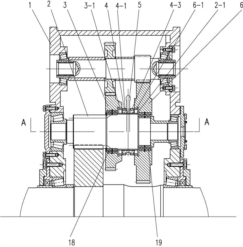
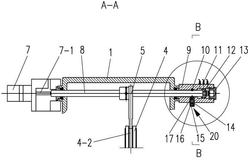
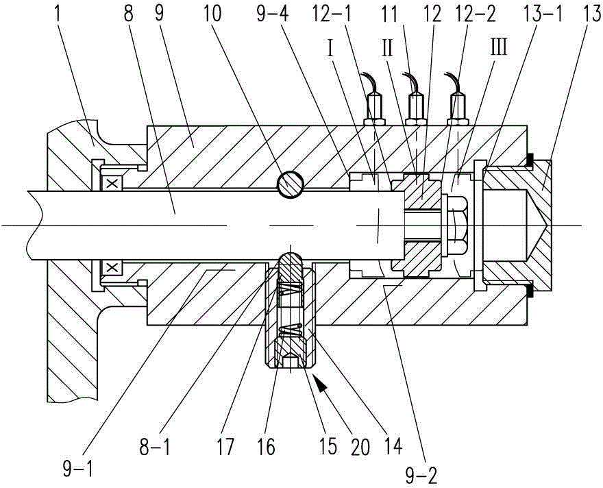
[0019] Such as figure 1 , 2 , 3, 4, 5, and 6, a shift locking mechanism of the present invention includes a case body 1, a toggle mechanism, an engaging sleeve 4, a locking mechanism, a gear shaft 2, and the first driven gear 3 and the second Driven gear 6, the toggle mechanism is mounted on the casing 1 and is connected to the engagement sleeve 4, the locking mechanism is mounted on the casing 1, and the engagement sleeve 4 has an internal spline 4-4, so The gear shaft 2 has an external spline 2-1, the internal spline 4-4 of the meshing sleeve 4 is in constant mesh and sliding fit with the external spline 2-1 of the gear shaft 2, and the first driven gear 3 passes through the first A bearing 18 is rotatably supported on the gear shaft 2, the first driven gear 3 has a first internal spline 3-1, and the second driven gear 6 is rotatably supported on the gear shaft 2 through the second bearing 19, The second driven gear 6 has a second internal spline 6-1, and the two ends of t...


PUM


Abstract

The invention discloses a gear shifting locking mechanism of railway large track maintenance machinery gear box. The gear shifting locking mechanism comprises a box, a shifting mechanism, an engaging sleeve, a locking mechanism, a gear shaft, a first driven gear and a second driven gear. The inner spline of the engaging sleeve is normally engaged with and in slide fit with the outer spline of the gear shaft. The first driven gear is rotatably supported on the gear shaft through a first bearing. The first driven gear is provided with a first inner spline. The second driven gear is rotatably supported on the gear shaft through a second bearing. The second driven gear is provided with a second inner spline. Two ends of the engaging sleeve are respectively provided with a first outer spline and a second outer spline. When the engaging sleeve moves on the gear shaft, the first outer spline of the engaging sleeve can be engaged with or separated from the first inner spline of the first driven gear. The second outer spline of the engaging sleeve can be engaged with or separated from the second inner spline of the second driven gear. The gear shifting locking mechanism is stable in gear shifting, reliable in locking, safe and convenient to operate, reasonable in structure and easy to manufacture and mount.

Description

technical field [0001] The invention relates to an axle gear box of a large-scale railway track maintenance machine, in particular to a shifting mechanism of the gear box. Background technique [0002] According to the requirements of different working conditions, the gear box realizes gear conversion through the gear shifting mechanism. In order to prevent accidental movement of the gear position, a gear locking mechanism is provided. There are two ways of shifting and locking mechanism of the existing hydraulically driven gearbox: one is the 08-32 type tamping vehicle auxiliary drive axle gearbox introduced from Plasser﹠Theurer company, which shifts gears by means of toggle gears , it uses the cylinder to push the shift fork, and the shift fork drives the gear to move on the spline shaft to realize the gear shift. Due to the small gear meshing backlash, it is difficult for the driving gear to be inserted into the driven gear accurately when shifting gears. Inconvenient; t...

Claims


Application Information

Patent Timeline
IPC IPC(8): F16H59/02F16H63/34F16H63/32
CPCF16H59/02F16H59/0278F16H63/32F16H63/34F16H2059/0282F16H2063/325
Inventor 张志强丁忍张磊
Owner CHANGZHOU RUITAI ENG MASCH CO LTD
Why Eureka
Try Eureka