Sliding interface cover plate structure

A sliding, interface technology, applied in the field of sliding interface cover structure, can solve the problems of the cover structure cannot be opened, lost, difficult to assemble, etc.

Inactive Publication Date: 2014-07-09
HUANDA COMPUTER (SHANGHAI) CO LTD +1
View PDF0 Cites 0 Cited by
  • Summary
  • Abstract
  • Description
  • Claims
  • Application Information

AI Technical Summary

Problems solved by technology

[0005] However, the existing cover plate structure cannot be opened due to interference, and it is difficult to assemble, and the cover plate is easily lost due to excessive force when the cover plate is pulled out after the assembly is completed.

Method used


Image

  • Sliding interface cover plate structure
  • Sliding interface cover plate structure
  • Sliding interface cover plate structure

Examples


Embodiment Construction

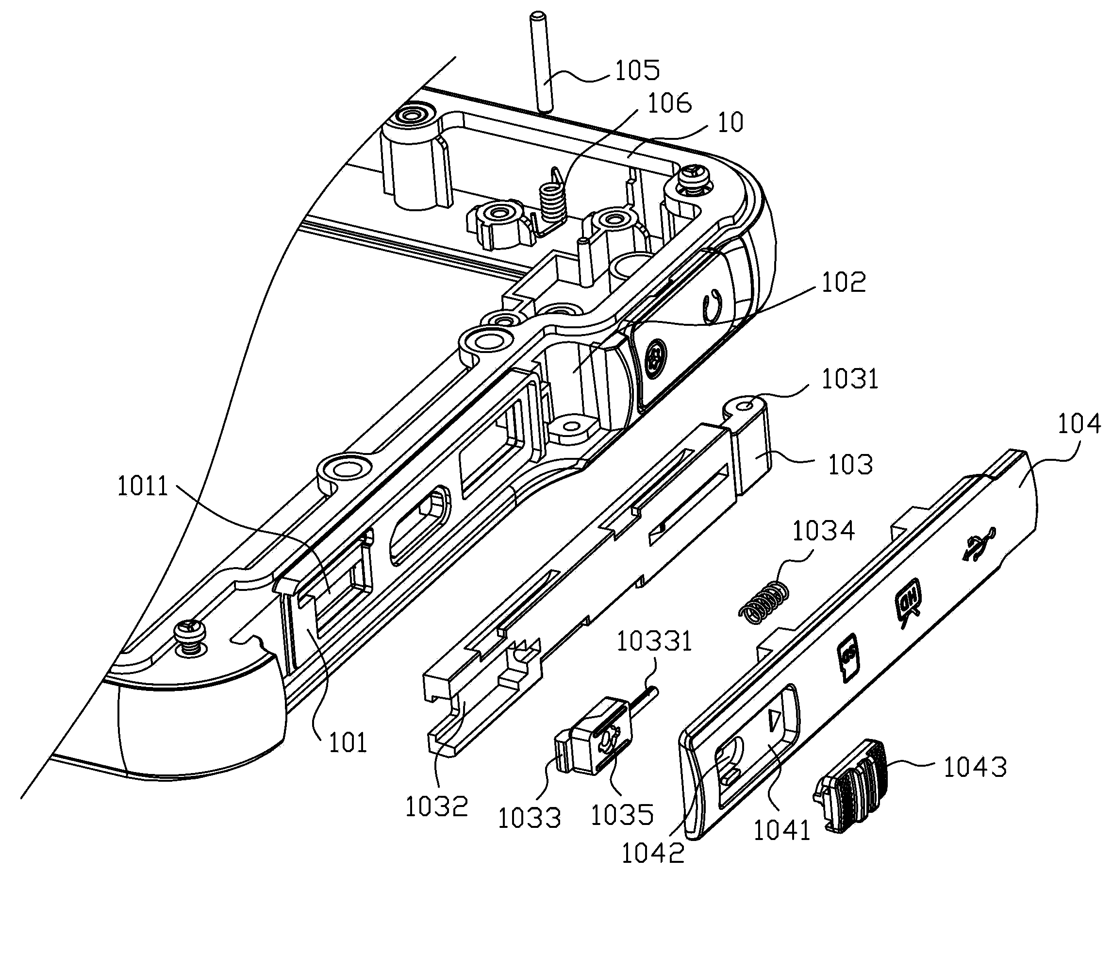
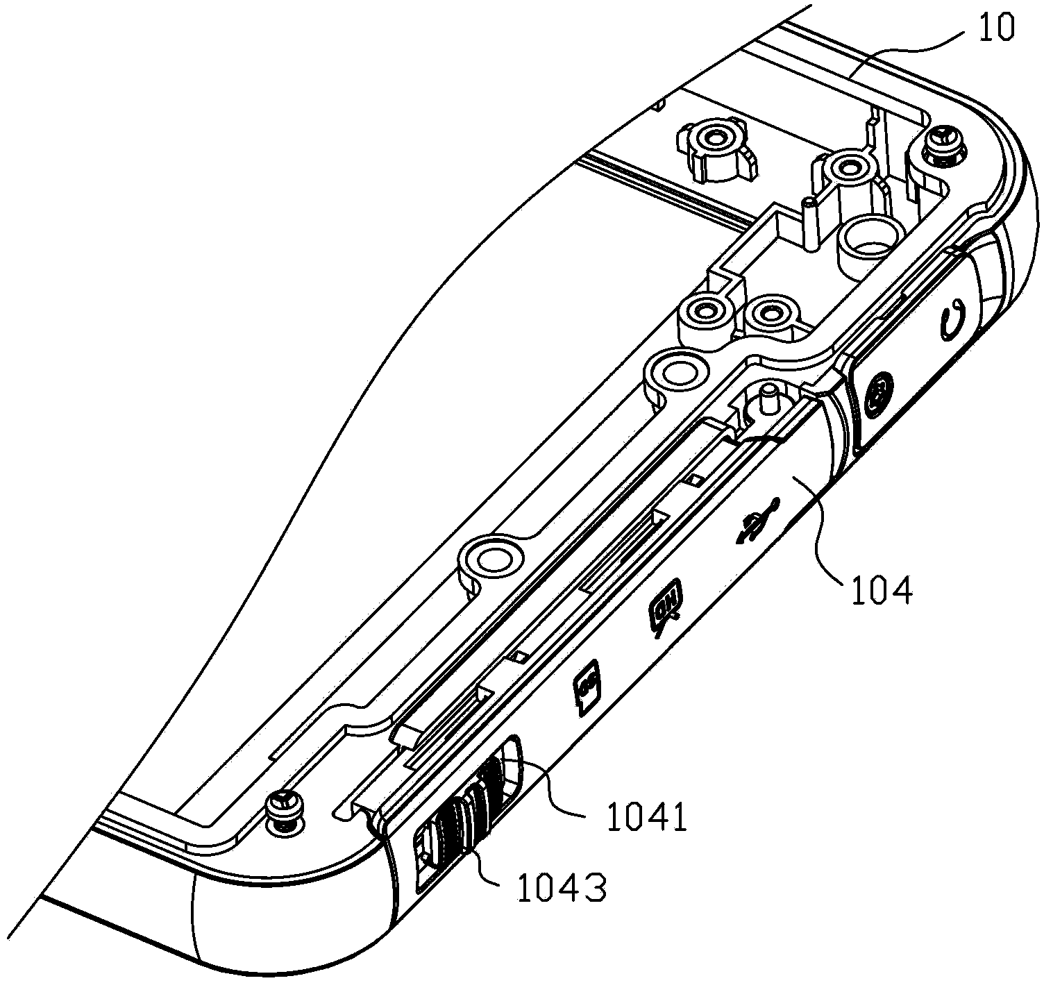
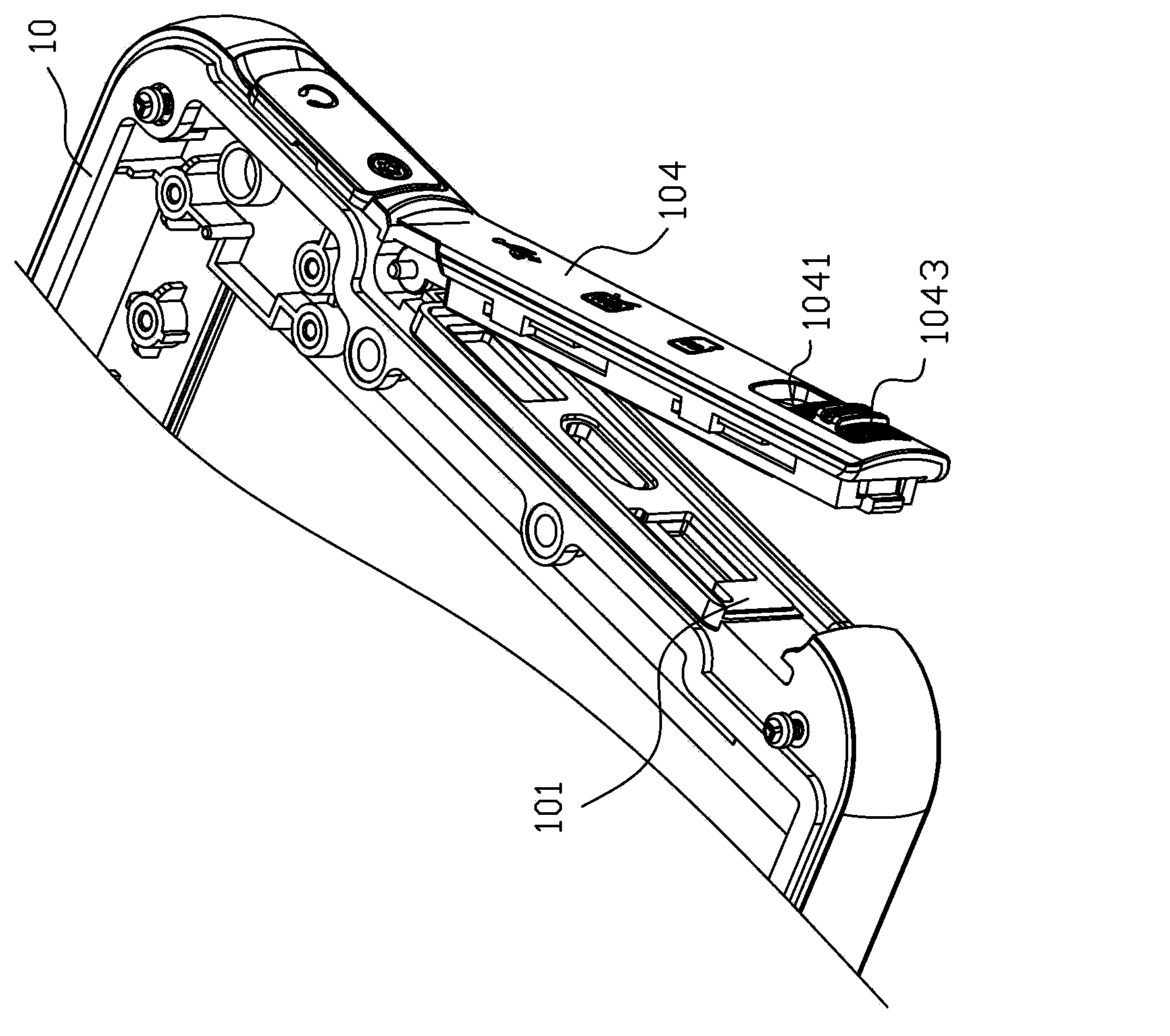
[0016] Please refer to Figure 1 to Figure 4 As shown, the present invention provides a sliding interface cover structure, which is suitable for closing the output / input interface 1011 of the portable electronic device 10, so as to prevent dust and other substances from falling into the output / input interface when the output / input interface is not in use. , the sliding interface cover structure is set at the interface position on one side of the casing of the portable electronic device 10 .

[0017] Wherein, the sliding interface cover structure mainly includes an accommodating groove 101, a rotating groove 102, an inner cover 103 and an outer cover 104, and the accommodating groove 101 is arranged at the interface position of the side of the housing so that the interface 1011 is exposed. In the accommodating tank 101 ; the rotating tank 102 is disposed adjacent to one end of the accommodating tank 101 .

[0018] Moreover, the inner cover 103 is placed in the accommodatin...


PUM


Abstract

The invention provides a sliding interface cover plate structure used for closing an interface position disposed on a side surface of a housing of a portable electronic device. The sliding interface cover plate structure comprises a containing groove, a rotating groove, an inner cover, and an outer cover. The containing groove is disposed in the interface position on the side surface of the housing. The rotating groove is disposed adjacent to one tail end of the containing groove. The inner cover is placed in the containing groove. One tail end of the inner cover is a rotating shaft sleeved by a torsion spring. The rotating shaft is fixed on the rotating groove in order to enable the tail end of the inner cover to be pivoted on the rotating groove. An inner sliding knob is disposed on the other tail end of the inner cover. A side of the inner sliding knob is provided with a fixing shaft sleeved by an elastic assembly. An outer sliding groove is disposed in the outer side surface of the outer cover and is equipped with an outer sliding knob combined with and fixed on the inner sliding knob. The invention solves the problem that an interface cover plate cannot be opened because of interference. The inner cover is rotated by using the torsion force of the torsion spring so that the outer cover contacts an interference point. Therefore, the outer cover is further pushed to slide laterally, and the interface cover plate is smoothly opened.

Description

[0001] technical field [0002] The invention relates to an interface cover structure, in particular to a sliding interface cover structure suitable for the output / input interface of a portable electronic device. [0003] Background technique [0004] Existing portable electronic devices are formed with openings for connecting IF connectors, memory or USB, etc. for connection terminals for data input / output at a predetermined position of the casing. Here, the predetermined position of the casing is generally formed on the side of the casing. , below, etc., in order to prevent dust and other substances from falling into the interface when the interface is not in use, a cover plate is usually provided at the interface. [0005] However, the existing cover structure cannot be opened due to interference, and it is difficult to assemble, and the cover is easily lost due to excessive force when the cover is pulled out after assembly. [0006] Contents of the invention ...

Claims


Application Information

Patent Timeline
IPC IPC(8): H01R13/52
Inventor 林柏汉
Owner HUANDA COMPUTER (SHANGHAI) CO LTD
Why Eureka
Try Eureka