Control connecting device for detecting lens of electronic control camera

A lens detection and connection device technology, applied in the field of signal transmission, can solve problems such as the inability to obtain control protocol signals, and achieve the effect of effective transmission without distortion and guaranteed connection

Pending Publication Date: 2021-12-31
杭州国照检测技术有限公司
View PDF0 Cites 0 Cited by
  • Summary
  • Abstract
  • Description
  • Claims
  • Application Information

AI Technical Summary

Problems solved by technology

[0003] Aiming at the problem that the electronically controlled camera lens needs to be disengaged from the fuselage during the parameter test, resulting in the inability to obtain the control protocol signal of the fuselage, the present invention provides a control connection device for electronically controlled camera lens detection, and the included angle is designed For the 120-degree positioning concave claw connection and fixation of the electronically controlled camera lens to be tested, the corresponding design of the 120-degree positioning claw connection and fixed camera body, through the connection of contacts and contacts to obtain effective transmission of control signals, Make the lens obtain the corresponding control signal to get normal opening and other controls, and finally realize the detection of lens parameters

Method used


Image

  • Control connecting device for detecting lens of electronic control camera
  • Control connecting device for detecting lens of electronic control camera

Examples


Embodiment Construction

[0016] The present invention will be further described below in conjunction with the accompanying drawings.

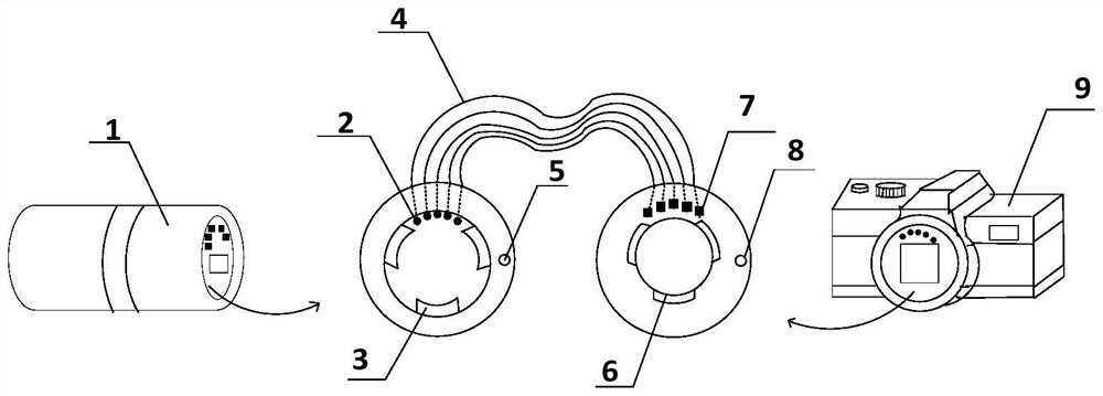
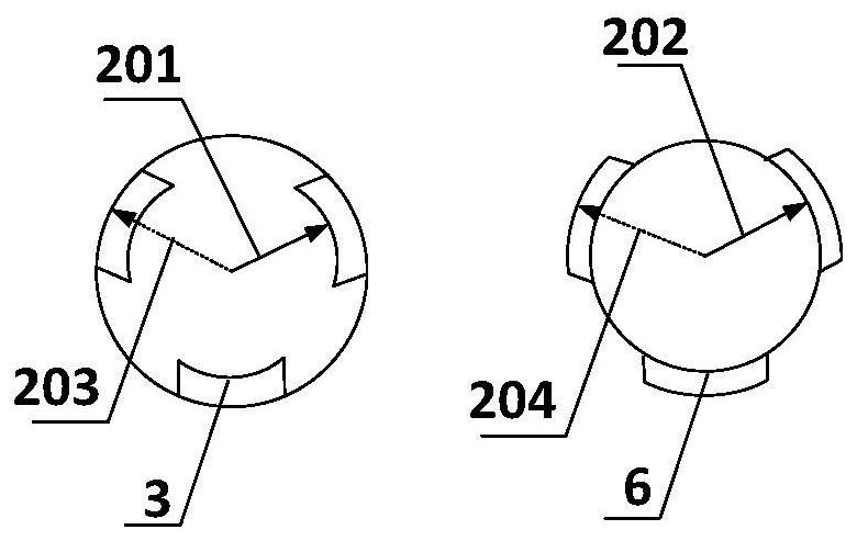
[0017] Such as figure 1 As shown, a control connection device for electronically controlled camera lens detection is characterized in that it includes a contact (2), a positioning claw (3), a cable (4), a limit hole (5), and a positioning claw (6), contact piece (7), limit pin (8); the electronic control camera lens (1) to be tested is connected with the positioning concave claw (3), and the positioning concave claw (3) is connected with the positioning convex through the cable (4) Claw (6) links to each other, and positioning lug (6) links to each other with camera body (9). The above-mentioned positioning concave claw (3) and positioning convex claw (6) have three positioning claws, and the three claws are arranged at 120°; the outer edges of the positioning concave claw (3) and the positioning convex claw (6) are in the same circle and The circles are equal in dia...


PUM


Abstract

The invention discloses a control connecting device for detecting an electric control camera lens. The whole device is composed of a machine body end positioning convex claw, a lens end positioning concave claw, a limiting hole, a contact, a contact piece, a limiting pin and a flat cable. When the to-be-tested electrically-controlled camera lens leaves the camera body for testing, the positioning concave claw is connected with the electrically-controlled camera lens, the positioning convex claw is connected with the camera body, and the electrically-controlled camera lens separated from the camera body obtains a control signal transmitted by the camera body through a flat cable, so that control on parameters such as opening, closing, size, focusing and zooming of an aperture of the electrically-controlled camera lens is realized. The device has the advantages that: the problem that a control signal cannot be obtained after the electronic control camera lens is separated from the machine body during detection is solved, the separated electronic control camera lens and the machine body are connected through the positioning convex claw and the positioning concave claw, the control signal of the machine body is indirectly obtained through the flat cable, a solution is provided for detection of the electronic control camera lens, and the test of the lens parameters is more convenient.

Description

technical field [0001] The invention belongs to the field of signal transmission and camera detection, and in particular relates to a control connection device for electronically controlled camera lens detection. Background technique [0002] Digital cameras use image sensors instead of traditional film, so the structure of the body is very different. When testing the lens, it is impossible to open the back cover of the film to directly obtain the optical signal like the traditional camera, so it needs to be compared with the camera when testing the lens. The fuselage is separated, but in this way, the lens cannot obtain the control signal sent by the fuselage, so that the lens is in a closed state, and the detection of various performances of the lens cannot be completed. The invention proposes a control connection device for electronically controlled camera lens detection, which can enable the lens to obtain the control signal transmitted by the body after the lens is deta...

Claims


Application Information

Patent Timeline
Patent Type & Authority Applications(China)
IPC IPC(8): H04N17/00
CPCH04N17/002
Inventor 王林杨春君程一凡王均杨伟庚李可王卓程
Owner 杭州国照检测技术有限公司
Why Eureka
Try Eureka