Flanging and patting device for metal thin-walled cylindrical vessels

A thin metal and cylindrical technology, applied in the field of flanging and flattening devices for metal thin-walled cylindrical vessels, can solve the problems of expensive mold material processing costs, occupation of production time and labor, and long manufacturing cycle, so as to achieve convenient and rapid production and save Improvement in installation and commissioning time and production efficiency

Inactive Publication Date: 2014-07-16
刘英
View PDF0 Cites 6 Cited by
  • Summary
  • Abstract
  • Description
  • Claims
  • Application Information

AI Technical Summary

Problems solved by technology

[0004] The above method is an existing common technical means, because the mode of mutual extrusion of the convex and concave dies used in it forces the bending and deformation of the cylindrical vessel, and its structure is fixed, so it can only be applied to products of the same model size, and the scope of application is single; and when the cylindrical vessel When there are multiple models, it is necessary to manufacture multiple sets of convex and concave molds at the same time, and it needs to occupy multiple stretching machines; and the manufacturing cycle of a set of convex and concave molds is longer, and the mold materials and processing costs are more expensive, resulting in capital and equipment costs. waste; when changing the production of different types of cylindrical vessels, it is necessary to replace the convex and concave molds and debug, which takes up production time and labor, resulting in unnecessary time and labor waste; and the convex and concave molds take a long time in the process of opening and closing the mold. Wasted production time, low production efficiency

Method used


Image

  • Flanging and patting device for metal thin-walled cylindrical vessels
  • Flanging and patting device for metal thin-walled cylindrical vessels
  • Flanging and patting device for metal thin-walled cylindrical vessels

Examples


Embodiment Construction

[0029] In order to enable those skilled in the art to better understand the technical solution of the present invention, the present invention will be described in detail below in conjunction with the accompanying drawings. The description in this part is only exemplary and explanatory, and should not have any limiting effect on the protection scope of the present invention. .

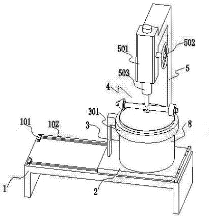
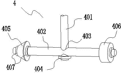
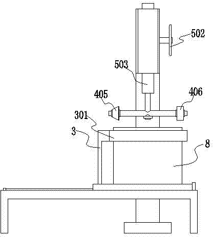
[0030] Such as Figure 1-4 As shown, the connection relationship of the present invention is: it includes a base 1, a base plate 2 is provided on the base 1, a support 3 is provided on the base plate 2, and a support ring 301 is provided on the support 3; A molded body 4 is arranged above the bracket ring 301, and the molded body 4 is arranged on the rotating device 5; the molded body 1 includes a rotating shaft 401 connected to the rotating device 5, and a cross bar 402 connected below the rotating shaft 401, the A forming head 405 and a flattening head 406 are respectively provided at both ends of t...


PUM


Abstract

The invention belongs to the fields of metal material processing and mould manufacturing and discloses a flanging and patting device for metal thin-walled cylindrical vessels. The flanging and patting device comprises a base, a bottom plate is arranged on the base, a support is arranged on the bottom plate, and a support ring is arranged on the support. A moulding body is arranged above the support ring and on a rotary device. The moulding body comprises a rotating shaft connected to the rotary device and a cross bar connected to the lower side of the rotating shaft, and a moulding head and a leveling head are respectively arranged at two ends of the cross bar. The flanging and patting device is simple in mechanism, low in material cost, short in manufacturing circle, applicable to flanging and patting the cylindrical vessels different in size, reduced in mounting time and high in processing speed and production efficiency.

Description

technical field [0001] The invention belongs to the field of metal material processing and mold manufacturing, in particular to a flanging and flattening device for metal thin-walled cylindrical vessels. Background technique [0002] The basic condition of metal material flanging is the plastic deformation of the material, that is, the performance of permanent deformation under the condition that the integrity is not damaged. Flanging is a common processing method in industrial applications. [0003] In the daily necessities industry, especially in the home appliance manufacturing industry, it is often necessary to manufacture cylindrical containers with flanging and flattening, that is, the flanging is approximately perpendicular to the body of the cylindrical container, and the bending position is approximately 90°, so as to obtain the flanging Or hanging ears; its products include the body of the electric kettle, the liner of the electric kettle, etc. In addition, becau...

Claims


Application Information

Patent Timeline
Patent Type & Authority Applications(China)
IPC IPC(8): B21D19/02
Inventor 陈龙刘英陈廷锴
Owner 刘英
Why Eureka
Try Eureka