
Locating mechanism

A technology of positioning mechanism and fixing plate, applied in workpiece clamping devices, manufacturing tools, etc., can solve the problems of high labor intensity, inaccurate positioning of push rods, affecting the quality of pressed products, etc., to ensure the quality and positioning of pressed products. Product accurate results

Active Publication Date: 2014-07-16
BOZHON PRECISION IND TECH CO LTD
View PDF5 Cites 11 Cited by
  • Summary
  • Abstract
  • Description
  • Claims
  • Application Information

AI Technical Summary

Problems solved by technology

[0002] When pressing the product and parts, it is necessary to position the product, and sometimes a positioning mechanism that uses the push rod to move forward to withstand the product to achieve positioning is required. In the prior art, it is generally manual operation, and the push rod will swing Causes inaccurate positioning, affects the quality of pressed products, and manual operation is labor-intensive

Method used


Image

  • Locating mechanism

Examples


Embodiment Construction

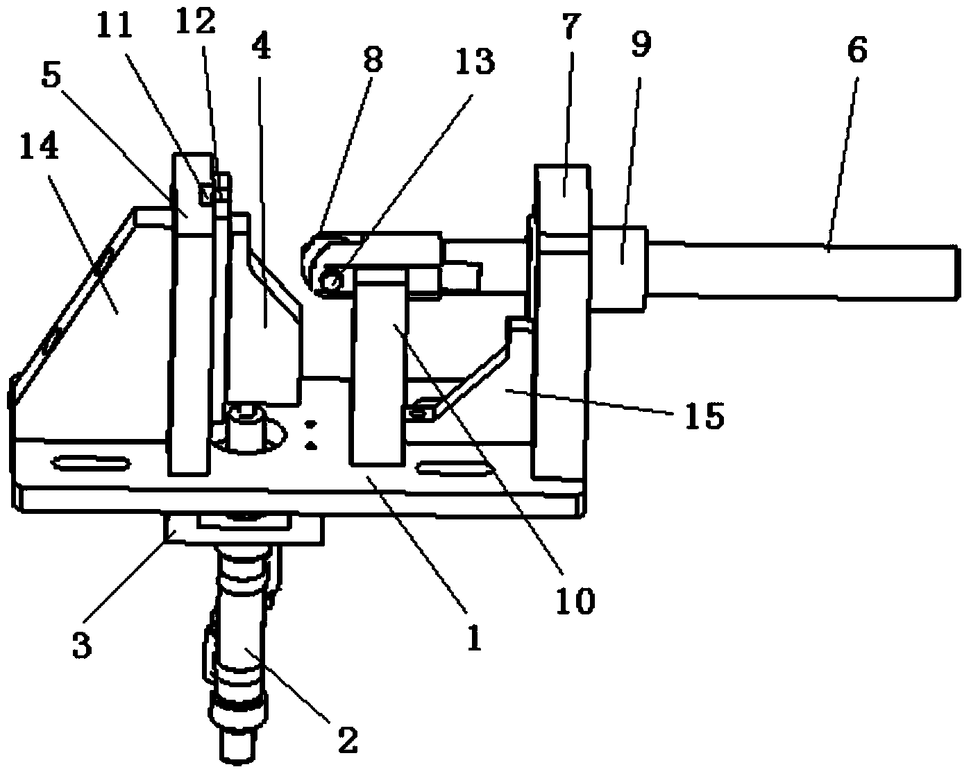
[0013] Examples, see attached figure 1 , a positioning mechanism, which includes a base plate 1, a cam lift cylinder 2, a lift cylinder fixed plate 3, a cam 4, a cam baffle plate 5, a push rod 6, a push rod support plate 7, a roller 8, a linear bearing 9 and a block 10 , the lifting cylinder fixing plate is installed on the bottom of the base plate, and the cam lifting cylinder is installed on the lifting cylinder fixing plate; the lifting rod of the cam lifting cylinder passes through the base plate and is connected with the cam; the base plate is fixedly equipped with a cam stop There is a slide rail 11 on the cam baffle, and a slide plate 12 is provided on the cam. The slide rail and the slide plate are installed together. When the cam lifting cylinder pushes the lifting rod to move up and down, the cam can move up and down along the slide rail to ensure that the cam Stability and direction of movement; the push rod support plate is installed on the base plate, a linear bea...


PUM


Abstract

The invention relates to a locating mechanism. A lifting air cylinder fixing board of the locating mechanism is arranged at the bottom of a bottom board, and a cam lifting air cylinder is arranged on the lifting air cylinder fixing board; a lifting rod of the cam lifting air cylinder penetrates through the bottom board and is connected with a cam; the bottom board is fixedly provided with a cam baffle provided with a sliding rail, the cam is provided with a sliding board, and the sliding rail and the sliding board are arranged together in a matched mode; a pushing rod supporting board is arranged on the bottom board and provided with a linear bearing, the left end of a pushing rod is provided with an idler wheel through a rotary shaft, and the right end of the pushing rod penetrates through the linear bearing; the bottom board is further fixedly provided with a baffle block preventing the pushing rod from swinging; the cam lifting air cylinder acts to lift the cam along the sliding rail of the cam baffle, the cam makes contact with the idler wheel, the idler wheel rolls to enable the pushing rod to move forwards in the direction of the linear bearing, and a product is abutted to be located. According to the locating mechanism, the pushing rod can not swing, locating accuracy is achieved, and quality of the pressed product is high.

Description

Technical field: [0001] The invention relates to the field of positioning mechanism equipment, and more specifically relates to a positioning mechanism that can withstand products when products are pressed together. Background technique: [0002] When pressing the product and parts, it is necessary to position the product, and sometimes a positioning mechanism that uses the push rod to move forward to withstand the product to achieve positioning is required. In the prior art, it is generally manual operation, and the push rod will swing The positioning is inaccurate, which affects the quality of the pressed product, and the manual operation is labor-intensive. Invention content: [0003] The purpose of the present invention is to provide a positioning mechanism aimed at the deficiencies of the prior art. The push rod moves forward to withstand the product to achieve the purpose of positioning. The push rod will not swing, the positioning is accurate, and the quality of the...

Claims


Application Information

Patent Timeline
Patent Type & Authority Applications(China)
IPC IPC(8): B25B11/02B25B11/00
CPCB25B11/02
Inventor 吕绍林杨愉强吴小平贺鹏
Owner BOZHON PRECISION IND TECH CO LTD
Learn More