
Dual-cooling multi-channel pipeline system and its production process

A multi-channel tube and cooling channel technology, applied in the field of auto parts, can solve the problems of complex structure design of the cooling system, dead fire, engine burning in severe cases, leakage of medium in the tube, etc. The effect of small diameter change rate and small expansion of the pipe body

Active Publication Date: 2016-03-02
ZHEJIANG JUNHE RUBBER TECH
View PDF7 Cites 0 Cited by
  • Summary
  • Abstract
  • Description
  • Claims
  • Application Information

AI Technical Summary

Problems solved by technology

Due to the high technical content of the dual cooling system, the structural design of the entire cooling system is complex, so the number and structure of the cooling pipes are also numerous and complex. The dual cooling multi-channel piping system must not only ensure the flow of the medium in the pipe, but also ensure the sealing of the assembly Good performance, no leakage, at the same time, the rubber hose has good coolant resistance, ozone aging resistance and heat resistance, and can withstand a certain pressure. At the same time, it cannot interfere with and rub against other parts. The metal hardware rubs against the rubber tube for a long time, and the rubber tube is easily damaged. Furthermore, if each pipeline is directly assembled on the vehicle site, it will not only waste time, but also easily cause the medium in the tube to leak if there is an error or the connection is not firm during assembly. After the medium leaks, it affects the normal operation of the whole vehicle. In the light case, the car will die, and in the severe case, the engine will be burned down to the whole vehicle, threatening personal safety and poor car safety.

Method used


Image

  • Dual-cooling multi-channel pipeline system and its production process
  • Dual-cooling multi-channel pipeline system and its production process
  • Dual-cooling multi-channel pipeline system and its production process

Examples


Embodiment Construction

[0045] Embodiments of the present invention will be further described in detail below in conjunction with the accompanying drawings.

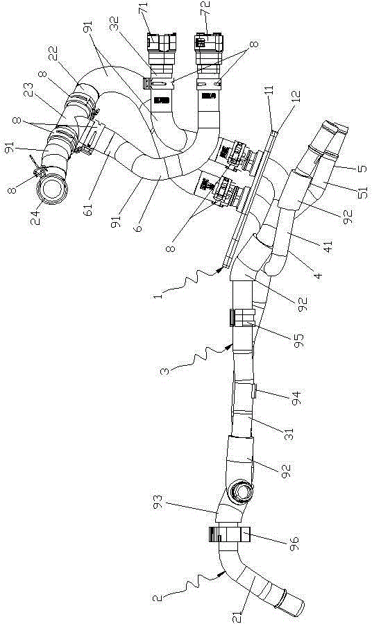
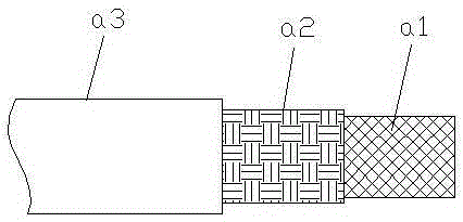
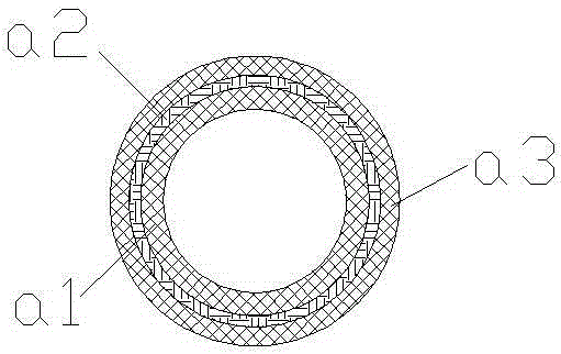
[0046] Figure 1 to Figure 3 Shown is the structural representation of the present invention.

[0047]The reference signs therein are: inner tube rubber layer a1, fiber thread reinforcement layer a2, outer tube rubber layer a3, bracket plate 1, metal plate 11, rubber plate 12, A-way cooling channel 2, first aluminum tube 21, First rubber tube 22, plastic tee tube 23, tail rubber tube 24, cooling channel B 3, second aluminum tube 31, second rubber tube 32, cooling channel C 4, first bypass aluminum tube 41. D-way cooling passage 5, second bypass aluminum pipe 51, E-way cooling passage 6, bypass rubber pipe 61, first straight pipe quick connector 72, second straight pipe quick connector 71, metal clamp 8. Rubber thermoplastic sheath 91 , rubber sheath 92 , sponge sheath 93 , first plastic bracket 94 , second plastic bracket 95 , first metal bra...


PUM


Abstract

The invention discloses a dual-cooling multi-channel pipeline system and a production process thereof. The system comprises a cooling channel A and a cooling channel B which are arranged on a fixing support plate. The cooling channel A is composed of a first aluminum pipe, a first rubber pipe, a three-way plastic pipe and a tail end rubber pipe, wherein the first aluminum pipe, the first rubber pipe, the three-way plastic pipe and the tail end rubber pipe are sequentially communicated. The cooling channel B is composed of a second aluminum pipe and a second rubber pipe, wherein the second aluminum pipe and the second rubber pipe are sequentially communicated. The first aluminum pipe is connected with a first by-pass aluminum pipe forming a cooling channel C and a second by-pass aluminum pipe forming a cooling channel D in a by-pass mode. The three-way plastic pipe is connected with a by-pass rubber pipe forming a cooling channel E. The first by-pass aluminum pipe and the second by-pass aluminum pipe are arranged on one side of the same end face of the support plate. The first rubber pipe and the second rubber pipe are arranged on one side of the other end face of the support plate. The first rubber pipe, the tail end rubber pipe, the second rubber pipe and the by-pass rubber pipe are rubber hoses made of EPDM rubber. The process method comprises the steps of preparing the rubber hoses and finished products.

Description

technical field [0001] The invention relates to the field of auto parts, in particular to a dual-cooling multi-channel pipeline system and its production process used in North American General Motors Cadillac models. Background technique [0002] The cooling device of the automobile engine is mainly cooled by water or antifreeze. It is cooled by the circulating water in the water channel of the cylinder, and the heated water in the water channel is introduced into the radiator (water tank), and then returned to the water channel after being cooled by wind. In order to ensure the cooling effect, the cooling system is generally composed of a radiator, a thermostat, a water pump, a water channel for the cylinder body, a water channel for the cylinder head, and a fan. The traditional engine is generally a single-cooling system. The engine only uses one thermostat, and the coolant in the cylinder block and cylinder head has only one circuit, and the temperature of the two coolant...

Claims


Application Information

Patent Timeline
Patent Type & Authority Patents(China)
IPC IPC(8): F01P11/04C08L23/16C08K5/14C08K5/09
Inventor 蒋亨雷王爱萍杨巍张帆杜文斌李东彪
Owner ZHEJIANG JUNHE RUBBER TECH
Learn More