Roof fairing, railway vehicle and roof fairing mounting method
A technology of a rail vehicle and an installation method, which is applied in the direction of railway car body, railway roof, transportation and packaging, etc., can solve the problem of inability to install the roof shroud, and achieve the effect of easy processing
- Summary
- Abstract
- Description
- Claims
- Application Information
AI Technical Summary
Problems solved by technology
Method used
Image
Examples
Embodiment 1
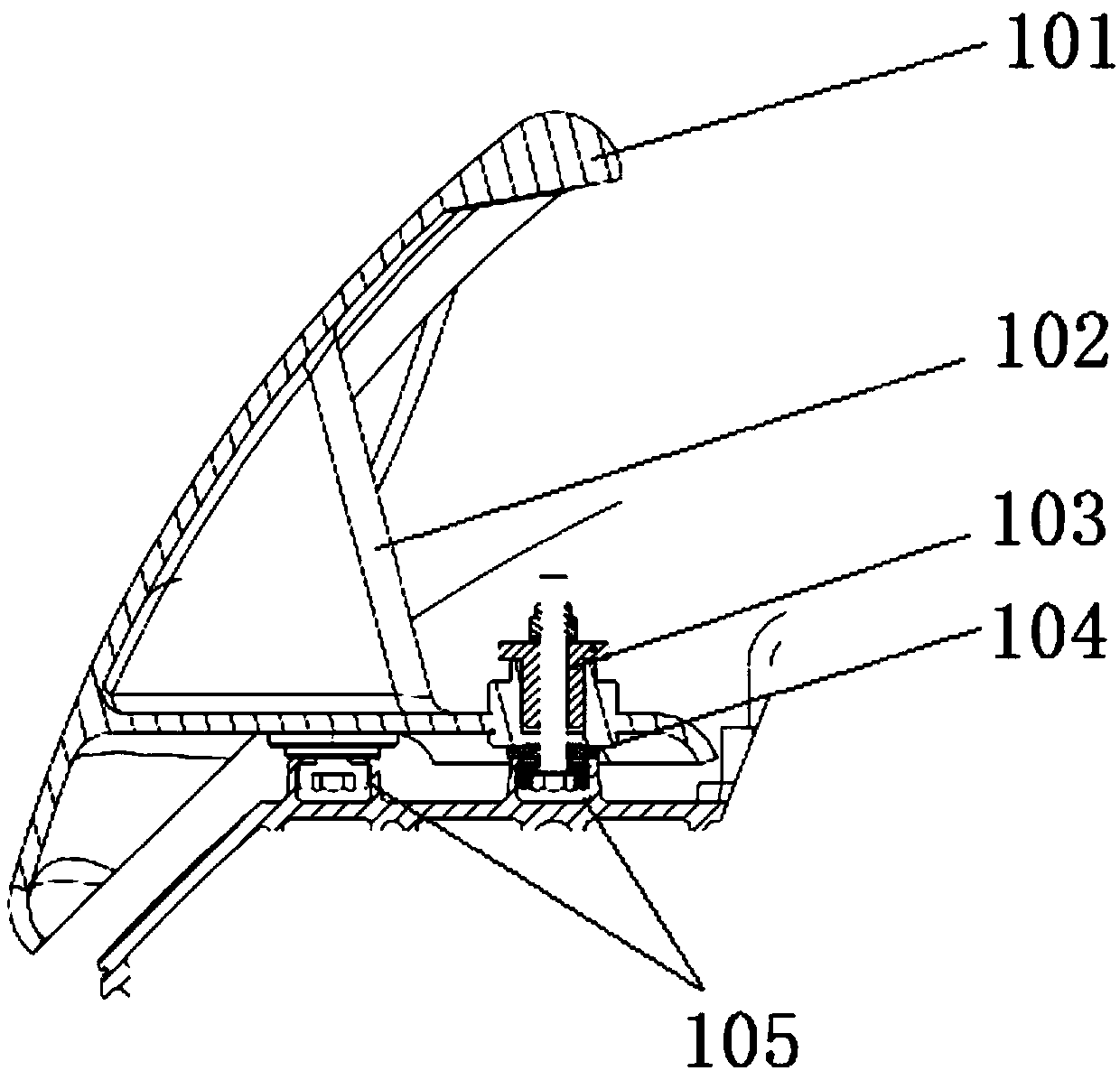
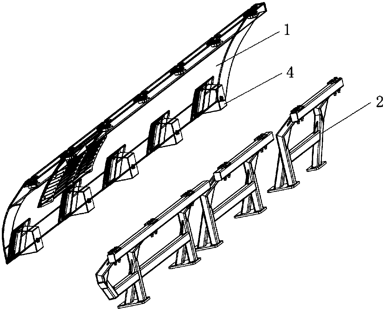
[0054] image 3 It is a schematic structural diagram of the roof deflector provided in Embodiment 1 of the present invention, Figure 4 An exploded view of parts of the shroud cover plate provided by Embodiment 1 of the present invention, Figure 5 It is a schematic diagram of the partial structure of the shroud cover plate provided by Embodiment 1 of the present invention, Image 6 It is a schematic diagram of a partial structure of a stent provided in Embodiment 1 of the present invention. Such as Figure 3-6 As shown, the roof spoiler provided by this embodiment is applied on rail vehicles, and includes a spoiler cover plate 1 and a bracket 2, the lower end of the bracket 2 is installed on the roof, and the upper end of the spoiler cover plate 1 and the upper end of the bracket 2 It is detachably connected, and the wind deflector cover plate 1 is located on the outside of the bracket 2, and the lower end of the wind deflector cover plate 1 is installed in the roof chute ...
Embodiment 2
[0076] Embodiment 2 of the present invention provides a rail vehicle, comprising a car body and the roof fairing according to any one of claims 1-8, the roof fairing is arranged on both sides of the car body, wherein the roof fairing The specific structure, working principle and functions of the system have been described in detail in the first embodiment above, and will not be repeated here.
[0077] Specifically, at least two rows of roof runners are arranged on the roof, and the roof deflector is installed in the roof runners through the connecting assembly.
[0078] The roof deflector provided by the present invention is applied on rail vehicles, and comprises a deflector cover plate and a bracket, the lower end of the bracket is installed on the roof, the upper end of the deflector cover plate is detachably connected with the upper end of the bracket, and the deflector cover The plate is located on the outside of the bracket, and the lower end of the fairing cover plate i...
Embodiment 3
[0080] Figure 7 It is a schematic diagram of installation of the roof deflector provided by Embodiment 3 of the present invention, Figure 8 The flow chart of the installation method for the roof deflector provided in Embodiment 3 of the present invention, as Figure 7-8 As shown, a method for installing a roof air deflector is applied to the roof air deflector according to any one of claims 1-8, and the installation method comprises the following steps:
[0081] Step 110, installing the lower end of the bracket 2 in the roof chute 3;
[0082] Step 120, connecting the upper end of the shroud cover plate 1 with the upper end of the bracket 2;
[0083] Step 130 , install the lower end of the wind deflector cover plate 1 in the roof runner 3 through the installation box 4 .
[0084] Specifically during the installation process, such as Figure 7 As shown, the two rows of roof chute 3 are provided with sliders, firstly adjust the sliders in the inner roof chute 3 to make it p...
PUM
 Abstract
Description
Claims
Application Information
 - R&D Engineer
- R&D Manager
- IP Professional
- Industry Leading Data Capabilities
- Powerful AI technology
- Patent DNA Extraction
Browse by: Latest US Patents, China's latest patents, Technical Efficacy Thesaurus, Application Domain, Technology Topic, Popular Technical Reports.
© 2024 PatSnap. All rights reserved.Legal|Privacy policy|Modern Slavery Act Transparency Statement|Sitemap|About US| Contact US: help@patsnap.com


