Running control method for fan group at condensing side of refrigeration system

A refrigeration system and operation control technology, applied in the field of control, can solve the problems of burning compressors, difference changes, large changes, etc., and achieve the effect of improving stability and smooth adjustment

Active Publication Date: 2014-07-16
GREE ELECTRIC APPLIANCES INC
View PDF10 Cites 12 Cited by
  • Summary
  • Abstract
  • Description
  • Claims
  • Application Information

AI Technical Summary

Problems solved by technology

In this way, even if the fan is started at the lowest gear speed in the low temperature environment (≤-5°C), or the speed of the fan is increased during operation, the high pressure of the refrigeration system will change instantaneously. The low pressure of the refrigeration system is usually relatively stable, which will cause the difference between the high pressure and the low pressure of the refrigeration system to change greatly in an instant
[0003] For example, for a screw compressor used in an air-cooled screw unit, at least the difference between the high pressure and the low pressure must be a

Method used


Image

  • Running control method for fan group at condensing side of refrigeration system
  • Running control method for fan group at condensing side of refrigeration system
  • Running control method for fan group at condensing side of refrigeration system

Examples


Embodiment 1

[0014] In the first embodiment of the present invention, taking the screw air-cooled water chiller as an example, the condensation side of the unit adopts an air-cooled heat exchanger, and the condensation side fan unit adopts 1 variable frequency fan and 3 fixed frequency fans.

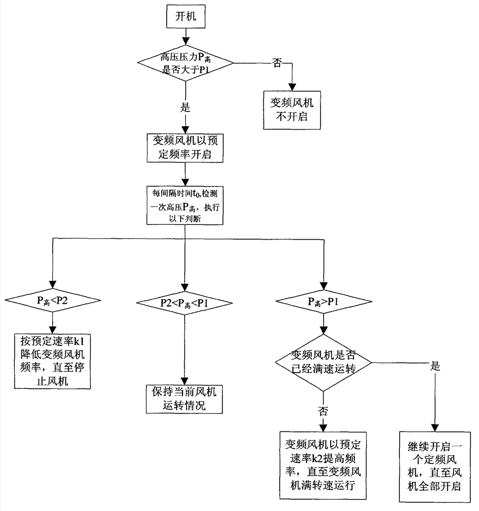
[0015] Set the high pressure P of the unit 高 The judgment reference value, the first reference value P1 is 14bar, the second reference value P2 is 9bar, the system high pressure protection pressure P 保 is 26bar; set the high pressure P of the unit 高 The detection interval time t 0 The applicant found that increasing the air volume of the condensing side fan unit can reduce the high pressure P of the refrigeration system 高 , reducing the air volume of the condensing side fan unit will increase the high pressure P 高 . In the first embodiment, the specific control method for the condensing side fan unit is as follows:

[0016] S1, start the unit;

[0017] S2. Detect high pressure P 高 , if P 高 >1...

Embodiment 2

[0025] In the second embodiment of the present invention, taking a screw air-cooled water chiller as an example, the condensation side of the unit adopts an air-cooled heat exchanger, and the condensation side fan unit adopts 1 variable-frequency fan and 3 fixed-frequency fans.

[0026] Set the high pressure P of the unit 高 The judgment reference value, the first reference value P1 is 9bar, the second reference value P2 is 14bar, the system high pressure protection pressure P 保 is 26bar; set the high pressure P of the unit 高 The detection interval time t 0 is 10s, the specific control method for the condensing side fan unit is as follows:

[0027] S1, start the unit;

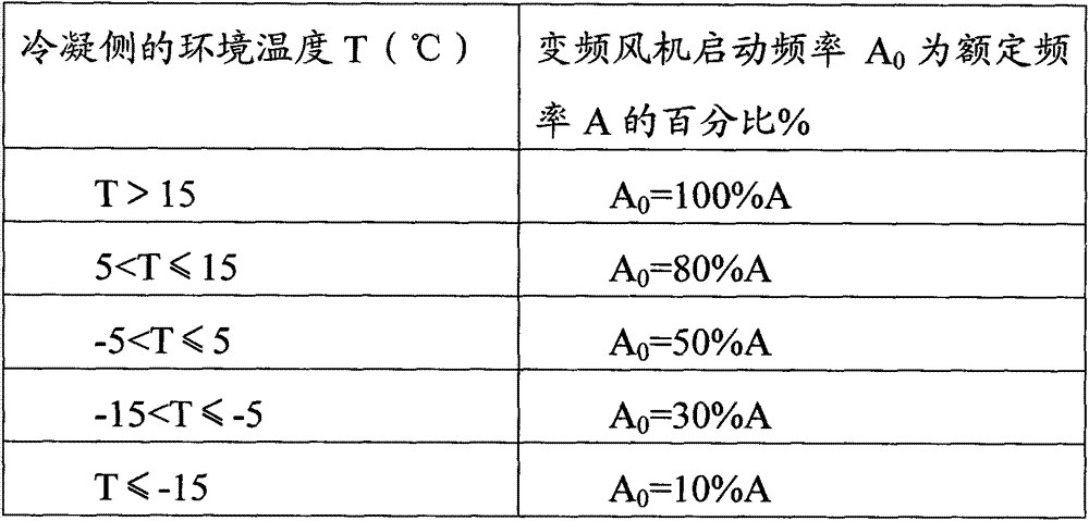
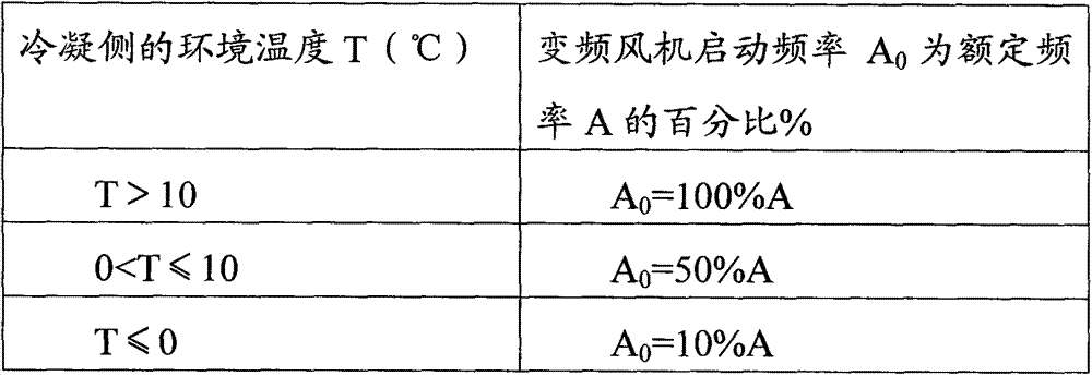
[0028] S2. Detect high pressure P 高 , if P 高 >14bar, then detect the ambient temperature T on the condensing side, and determine the starting frequency A of the variable frequency fan according to the range of the ambient temperature T on the condensing side 0 And start the frequency conversion fan; if P ...


PUM


Abstract

The invention discloses a running control method for a fan group at the condensing side of a refrigeration system. The fan group at the condensing side of the refrigeration system comprises a variable-frequency fan and at least one fixed-frequency fan. The control method comprises the following steps of: monitoring the high pressure P(high) of the system, judging with preset first reference value P1 and second reference value P2, judging whether the high pressure P(high) needs to be adjusted or not according to the interval where the high pressure P(high) is located, and realizing a stable adjustment on the high pressure P(high) by adjusting the running frequency of the variable-frequency fan at a preset speed while judging that the high pressure P(high) needs to be adjusted, thus avoiding the instability of the system due to the large changes of the high pressure P(high) in an instant, and then improving the running stability of the refrigeration system.

Description

technical field [0001] The invention relates to the field of control, in particular to a method for controlling the operation of a condensing side fan unit in a refrigeration system. Background technique [0002] At present, the fan on the condensing side of the refrigeration system mostly adopts an adjustable gear fan, and the start and stop of the fan is controlled by adjusting the gear of the fan. In this way, even if the fan is started at the lowest gear speed in the low temperature environment (≤-5°C), or the fan speed is increased during operation, it will cause a large instantaneous change in the high pressure of the refrigeration system. The low pressure of the refrigeration system is usually relatively stable, which will cause the difference between the high pressure and the low pressure of the refrigeration system to change greatly in an instant. [0003] For example, for the screw compressor used in the air-cooled screw unit, at least the difference between the h...

Claims


Application Information

Patent Timeline
IPC IPC(8): F25B49/02
Inventor 陈培生荣晓亮
Owner GREE ELECTRIC APPLIANCES INC
Why Eureka
Try Eureka