Adjustable recoil pad for a small arm

a recoil pad and small arm technology, applied in the direction of weapons, butts, weapons, etc., can solve the problem of not being able to easily change the desired adjustment, and achieve the effect of easy actuation, not readily changed, and simple adjustment of the inclination

Inactive Publication Date: 2009-05-26
BLASER FINANZHLDG
View PDF14 Cites 37 Cited by
  • Summary
  • Abstract
  • Description
  • Claims
  • Application Information

AI Technical Summary

Benefits of technology

[0006]In the recoil pad of the invention, a large number of adjustments can be undertaken in a relatively simple manner. By adjusting the connecting piece, it is possible to change, for example, the height of the recoil pad. The arrangement on the connecting piece of the bottom plate, which can be swivelled around a transverse axis, also makes possible a simple adjustment of the inclination of the bottom plate relative to the base plate. In this way, the so called pitch angle of the recoil pad can be adjusted. Also the base plate can be adjusted, for example, via oblong holes and corresponding retaining screws, on a stock part of the small arm. The base plate can thus be rotated within a predetermined angular range as well as displaced laterally. Thus, the offset of the recoil pad can be adjusted. The adjusting elements can be easily actuated and are extremely stable, so that a desired adjustment is not readily changed. In this way, it is possible to retain a desired adjustment permanently.
[0007]In a particularly expedient embodiment, the bottom plate comprises, above the transverse axis, a setscrew whose front end, protruding forwards, is pressed by at least one pressure spring, clamped between the bottom plate and the connecting piece. By adjusting the setscrew, it is thus possible to attain a very simple and nevertheless, stable incline adjustment of the recoil pad.
[0008]The transverse axis is preferably located above the middle axis of the bottom plate. A swivel movement of the recoil pad, caused by the recoil, thereby counteracts the kick of the weapon, and the moving axis of the small arm is more likely to remain in the desired target plane.
[0010]To lengthen or shorten the recoil pad, the end part, preferably constructed as an end cap, can be affixed to the bottom plate via one or more spacers. In another advantageous embodiment, passage openings, aligning spacers and the bottom plate with the retaining screws are provided in the end part. In this way, the retaining screws for adjusting the recoil pad are accessible from the outside, even without dismantling the end cap.

Problems solved by technology

The adjusting elements can be easily actuated and are extremely stable, so that a desired adjustment is not readily changed.

Method used


Image

  • Adjustable recoil pad for a small arm
  • Adjustable recoil pad for a small arm
  • Adjustable recoil pad for a small arm

Examples


Embodiment Construction

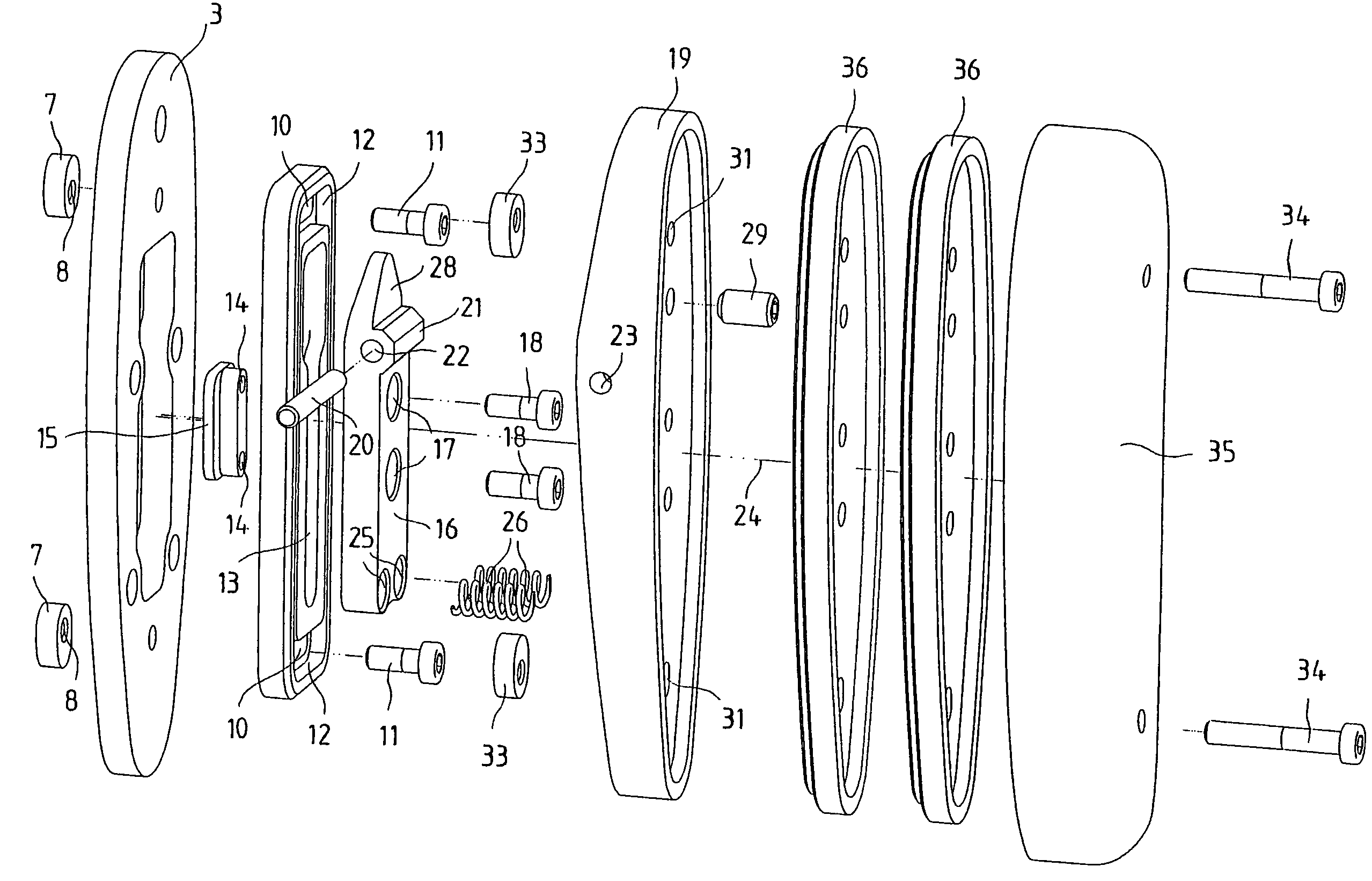
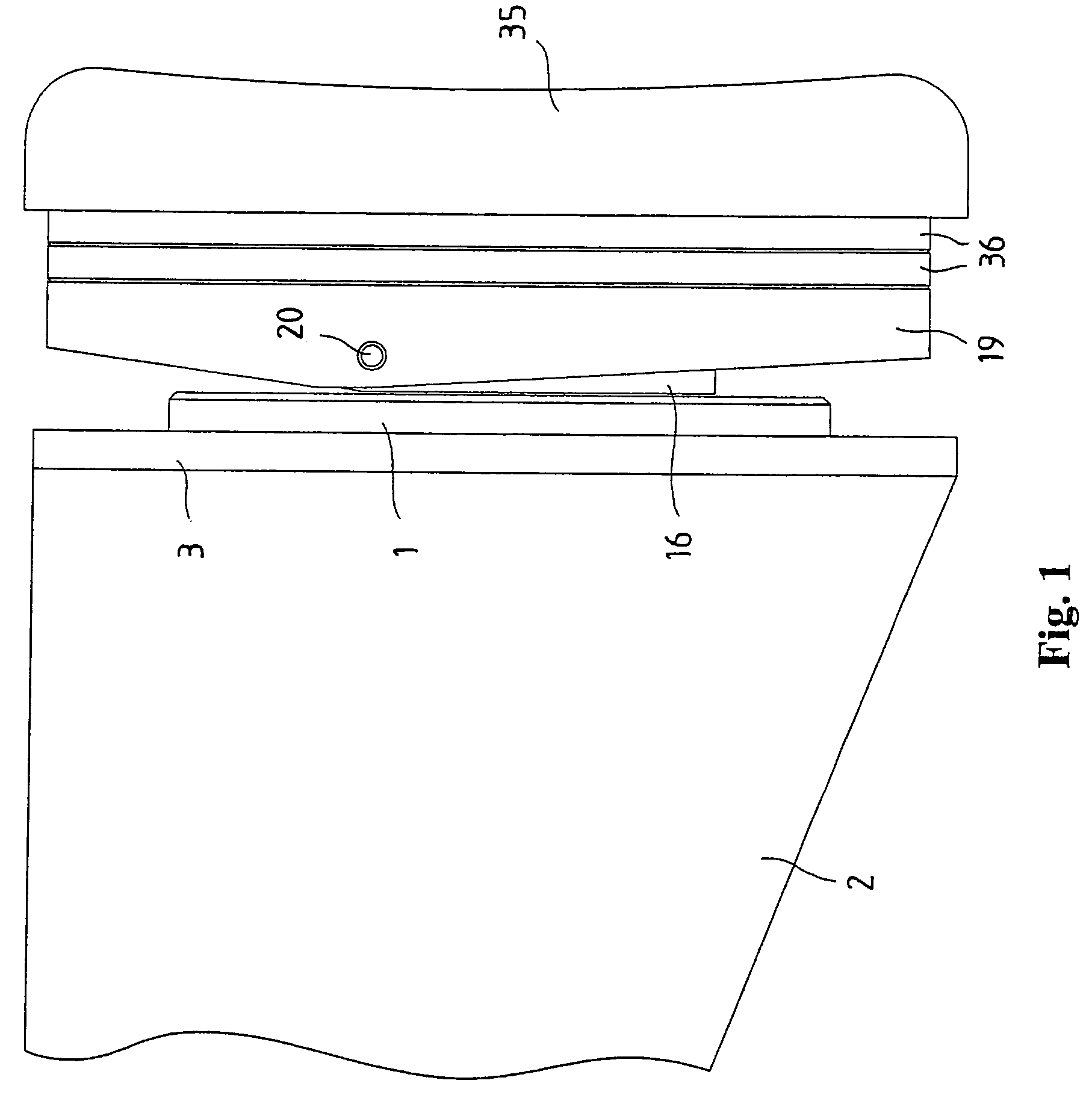
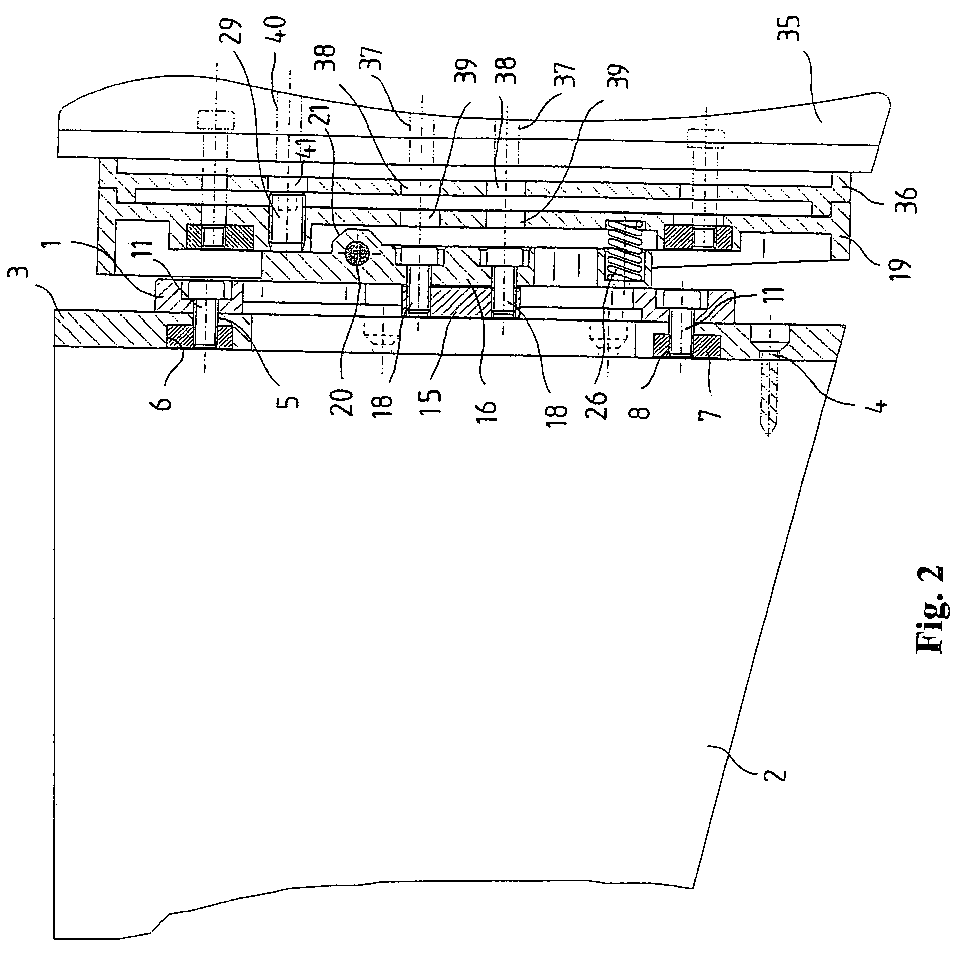
[0016]The recoil pad shown in FIGS. 1-4 comprises a base plate 1, which is adjustably affixed to a rear stock part 3, which is affixed on the rear end of a rear stock 2 and is constructed as a stock plate in the embodiment shown. The stock part 3, constructed as a stock plate and fitted to the outside contour of the rear stock 2, is affixed to the rear side of the rear stock 2 by screws 4, shown in FIG. 2. The stock part 3 comprises upper and lower passage openings 5, which have oval recesses 6, recognizable in FIG. 3, on the side pointing to the rear stock 2. Nuts 7 with an oval outside contour fitted to the inside contour of the recesses 6, and threaded holes 8 are located in the oval recesses 6.

[0017]As can be seen, in particular, from FIGS. 3 and 4, the base plate 1 has upper and lower transverse slots 10 for two retaining screws 11. The transverse slots 10 are constructed in the form of oblong holes with a recess 12, shown in FIG. 4, on the side used by the stock part 3. The ba...


PUM


Abstract

The invention concerns an adjustable recoil pad for a small arm, in particular, a rifle, with a base plate that can be adjustably affixed to a stock part of the small arm, a bottom plate which is adjustably mounted on the base plate, and at least one end part that can be affixed to the bottom plate. A simplified adjustment with a large number of adjustment possibilities is made possible in that the bottom plate is arranged so it can swivel about a transverse axis on a connecting piece, which is displaceably guided via guide elements on the base plate, and can be affixed in a desired position by at least one retaining screw.

Description

FIELD OF THE INVENTION[0001]The invention concerns an adjustable recoil pad for a small arm, in particular, a rifle.BACKGROUND OF THE INVENTION[0002]Such a recoil pad is known from DE 296 05 120 U1. The recoil pad described there is especially designed for sports shooters and constructed in such a way that the adjustability of the recoil pad can be suspended after a weapons inspection by a controllable blocking device. This should make it possible to check for compliance with competition rules during the competition. To this end, the recoil pad contains a base plate affixed to the rear end of a stock, on which base plate, an upper part, consisting of a middle part and wing parts affixed to it in a hinge like manner, is adjustably mounted. For the side adjustment of the recoil pad, additional threaded holes, within the sliding block, with stud screws countersinkable therein, are provided. By a corresponding adjustment of the two stud screws, it is possible to attain a lateral tilting...

Claims


Application Information

Patent Timeline
Patent Type & Authority Patents(United States)
IPC IPC(8): F41C23/00
CPCF41C23/14F41C23/20
Inventor POPIKOW, SERGEJ
Owner BLASER FINANZHLDG
Why Eureka
Try Eureka