
Eureka
For R&D, Eureka makes reading and utilizing patents & technical documents easy.
Eureka AIR
Designed for self-driven R&D workflows. Generate viable solutions, solve complex R&D challenges, empower your innovation with AI.

Eureka Materials
Designed for material experts only. Revolutionize your material R&D, from search, analyze, to developing new materials.

TechResearch
Generate reliable direction feasibility study reports for your R&D in just a few steps.

TechSeek
Discover and master advanced knowledge NOW. Basics, ideas, possibilities, all at once.

TechMind
As an expert in R&D Theories, TechMind can generates customized viable solutions instantly.

TechRisk
Analyze your overall solution with one click, know your potential R&D risks in advance.

TechMonitor
Get weekly tech updates, stay abreast of the latest tech innovations and key insights.
Multi-pass amplifying system for high-power laser separation chirp pulses
A chirped pulse and amplification system technology, which is applied in the field of high-power laser separation chirped pulse multi-pass amplification system, can solve problems such as insufficient power amplification capability, and achieve the effect of improving pulse amplification efficiency
- Summary
- Abstract
- Description
- Claims
- Application Information
AI Technical Summary
Problems solved by technology
Method used
Image

Examples
Embodiment Construction
[0018] The present invention will be further described below through examples and accompanying drawings, but the protection scope of the present invention should not be limited by this.
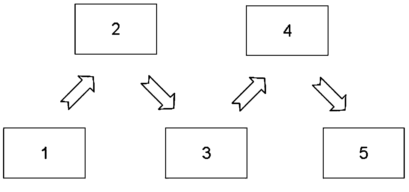
[0019] see first figure 1 , figure 1It is a schematic structural diagram of the high-power laser separation chirped pulse multi-pass amplification system of the present invention. As can be seen from the figure, the high-power laser separation chirped pulse multi-pass amplification system of the present invention is composed of a laser seed pulse source 1, a pulse stretcher 2, a DPA regeneration cavity 3, a double-pass DPA module 4 and a pulse compressor 5. The pulse source 1 outputs the seed pulse, which is broadened into a chirped pulse by the pulse stretcher 2, and then the power is amplified by the DPA regeneration cavity 3 and the double-pass DPA module 4, and finally the amplified chirped pulse is processed by the pulse compressor 5. compression. The pulse stretcher 2 and the pulse c...
PUM
 Abstract
Description
Claims
Application Information
 - R&D Engineer
- R&D Manager
- IP Professional
- Industry Leading Data Capabilities
- Powerful AI technology
- Patent DNA Extraction
Browse by: Latest US Patents, China's latest patents, Technical Efficacy Thesaurus, Application Domain, Technology Topic, Popular Technical Reports.
© 2024 PatSnap. All rights reserved.Legal|Privacy policy|Modern Slavery Act Transparency Statement|Sitemap|About US| Contact US: help@patsnap.com