Eureka AIR delivers breakthrough ideas for toughest innovation challenges, trusted by R&D personnel around the world.

Handlebar and head connecting mechanism

A technology for connecting mechanisms and handlebars, applied in steering mechanisms, bicycle accessories, transportation and packaging, etc., can solve the problems of poor firmness, short service life, and lack of positioning, etc. long life effect

Inactive Publication Date: 2014-07-30
重庆朔东汽车部件有限公司
View PDF10 Cites 1 Cited by
  • Summary
  • Abstract
  • Description
  • Claims
  • Application Information

AI Technical Summary

Problems solved by technology

But its disadvantage is that the design is not reasonable enough, and the positioning between the cannula and the cannula is not realized, the firmness is not good, and the service life is not long, so its structure still needs to be improved

Method used


Image

  • Handlebar and head connecting mechanism
  • Handlebar and head connecting mechanism
  • Handlebar and head connecting mechanism

Examples


Embodiment Construction

[0027] The present invention will be further described in detail below in conjunction with the accompanying drawings and embodiments.

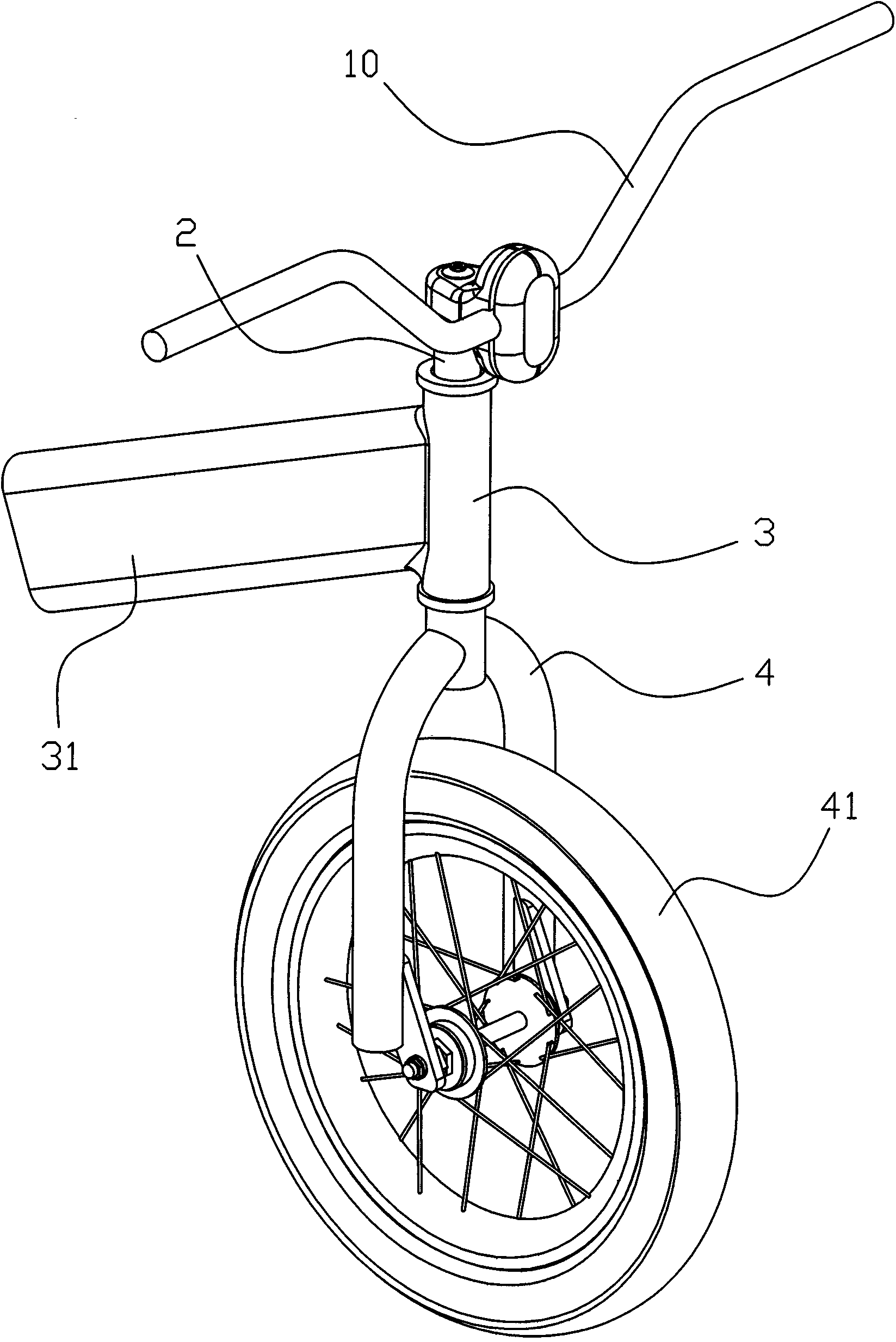
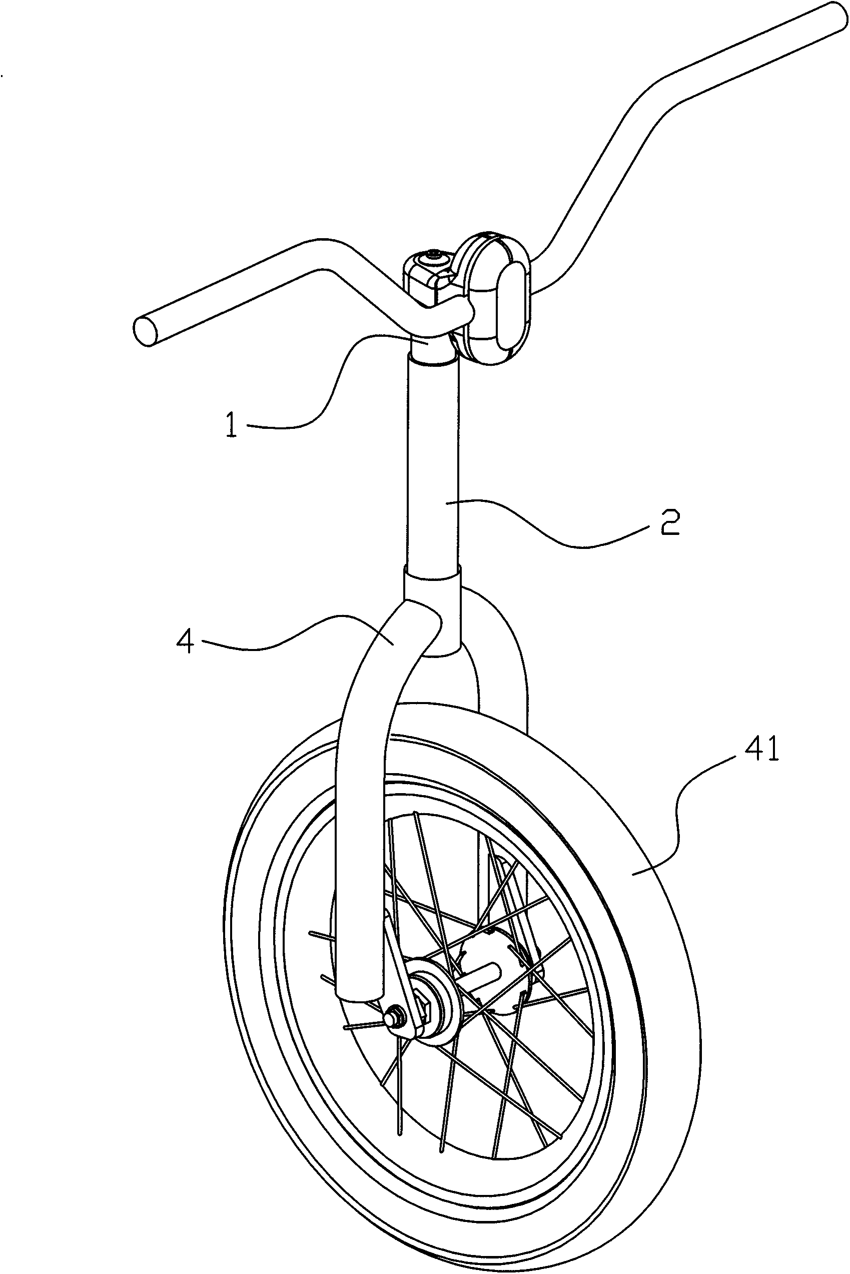
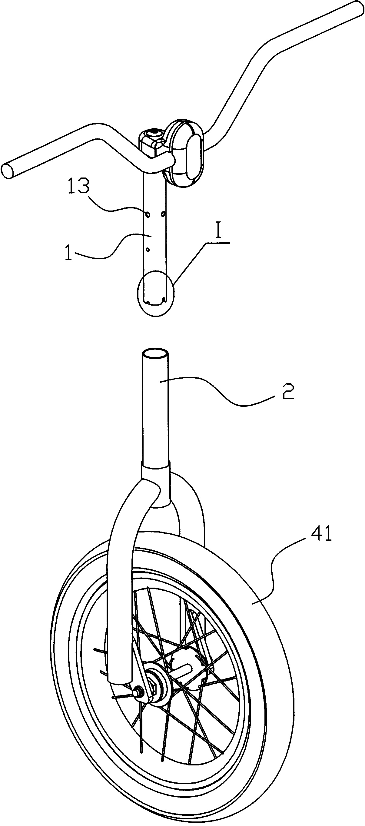
[0028] Such as Figure 1 to Figure 9 As shown, the connection mechanism between the handlebar and the headstock of the present embodiment includes an intubation pipe 1 whose upper end is fixed to the handle 10, and a sleeve pipe 2 whose lower end is fixed to the bracket 4 on which the front wheel 41 is installed. A sleeve 3 connected to the connecting frame 31 of the rear wheel is sleeved rotatably, a positioning rod 5 is arranged radially in the inner cavity of the lower part of the sleeve 2, and a positioning rod 5 that can be embedded in the positioning rod is provided on the lower end surface of the insertion tube 1. The gap 11 in 5 is provided with a detachment mechanism between the intubation tube 1 and the sleeve tube 2, which can be used to disengage the intubation tube 1 from the sleeve tube 2. When the intubation tube 1 is inserted i...


PUM


Abstract

The invention discloses a handlebar and head connecting mechanism, which comprises an inserted tube (1) and a bushing (2), wherein the bushing (2) is sleeved with a sleeve (3) connected with a connecting frame (31) of a rear wheel in a rotating way. The connecting mechanism is characterized in that a positioning rod (5) is radially arranged in a lower inner cavity of the bushing (2); gaps (11) into which the positioning rod (5) can be embedded are formed in the lower end face of the inserted tube (1); a disassembly mechanism capable of conveniently disassembling the inserted tube (1) from the bushing (2) is arranged between the inserted tube (1) and the bushing (2); when the inserted tube (1) is inserted into the bushing (2), the positioning rod (5) is embedded into the gaps (11) in the lower end face of the inserted tube (1) to fix together the inserted tube (1) with the bushing (2). The connecting mechanism has the advantages that a handlebar can be stably and firmly fixed together with a head only by inserting the inserted tube into the bushing, so that the condition of leftward and rightward rotation of the handlebar is completely eradicated, and the connecting mechanism can be conveniently and flexibly used, the service life is longer, and abrasion between the inserted tube and the bushing is further avoided.

Description

technical field [0001] The invention relates to the technical field of bicycle manufacture, in particular to a connection mechanism between a handlebar and a bicycle head. Background technique [0002] An existing Chinese utility model patent with application number CN201320083021.5 titled "Bicycle Handle Glove Locking Mechanism" discloses a structure, which is characterized in that: the locking mechanism includes a locking ring, a handlebar and a handlebar, One end surface of the locking ring is provided with a boss, and the end surface connecting the handle cover and the handrail is provided with a card slot, and the boss of the locking figure is inlaid with the card slot of the handle cover. There is a locking ring on the upper body, and the locking ring is arranged in the locking ring. The bicycle handlebar glove locking mechanism of the invention avoids the direct contact between the handlebar and the bicycle handlebar, thereby reducing the wear on the handlebar due to...

Claims


Application Information

Patent Timeline
Patent Type & Authority Applications(China)
IPC IPC(8): B62K21/16
Inventor 茅鸿勇
Owner 重庆朔东汽车部件有限公司
Why Eureka
Eureka Blog
Learn More