Capacitive touch system and driving device thereof

A technology of capacitive touch and driving device, which is applied in the fields of electrical digital data processing, instruments, and data processing input/output process, etc., can solve the problems of limited influence range and driving signal interference.

Active Publication Date: 2014-08-06
ILI TECHNOLOGY CORPORATION
View PDF6 Cites 0 Cited by
  • Summary
  • Abstract
  • Description
  • Claims
  • Application Information

AI Technical Summary

Problems solved by technology

That is to say, as long as the circuit adjacent to the sensing panel may be interfered by the driving signal, the range of influence is quite wide.

Method used


Image

  • Capacitive touch system and driving device thereof
  • Capacitive touch system and driving device thereof
  • Capacitive touch system and driving device thereof

Examples


Embodiment Construction

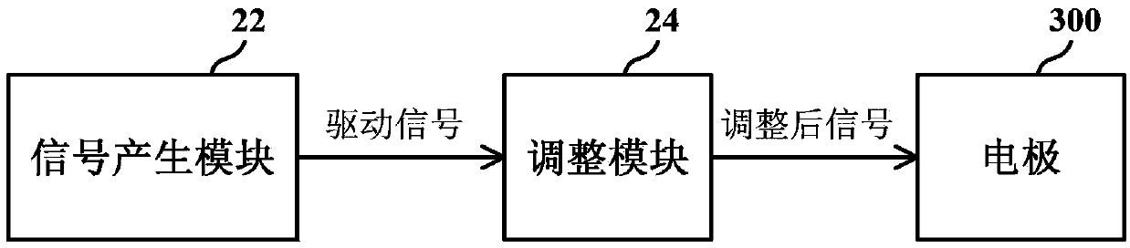
[0019] A specific embodiment according to the present invention is a driving device for cooperating with electrodes in a capacitive touch system, and its functional block diagram is as follows figure 2 shown. The drive device includes a signal generation module 22 and an adjustment module 24 . The signal generation module 22 is used to generate a driving signal VD. The adjusting module 24 connected between the electrode 300 and the signal generating module 22 is responsible for generating an adjusted signal VA according to the driving signal VD to replace the driving signal VD. like figure 2 As shown, the adjusted signal VA is used to drive the electrode 300 instead of the driving signal VD. Compared with the driving signal VD, the adjusted signal VA has less high-frequency components.

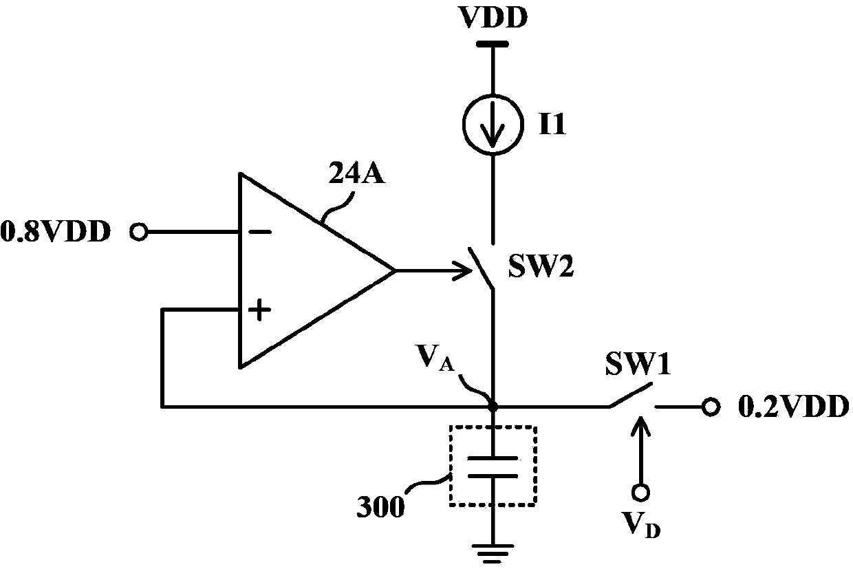
[0020] In one embodiment, the adjustment module 24 reduces the high-frequency components in the adjusted signal VA by reducing the rising slope of the adjusted signal VA. Figure 3A It ...


PUM


Abstract

The invention provides a driving device matched with an electrode in a capacitive touch system. The driving device comprises a signal generation module and an adjustment module, wherein the signal generation module is used for generating a driving signal; the adjustment module is connected between the electrode and the signal generation module, and is used for generating a post-adjustment signal according to the driving signal to replace the driving signal and controlling the waveform of the ascending edge or the descending edge of the post-adjustment signal to guarantee that fewer high-frequency components are in the post-adjustment signal relative to the driving signal.

Description

technical field [0001] The invention relates to a touch control system, in particular to an electrode driving device of a capacitive touch control system. Background technique [0002] With the advancement of technology, the operation interfaces of various electronic products have become more and more user-friendly in recent years. For example, through a touch screen, users can directly operate programs and input messages / texts / patterns on the screen with their fingers or a stylus, saving the trouble of using input devices such as keyboards or keys. Existing touch technologies are roughly classified into resistive, capacitive, electromagnetic induction, ultrasonic and optical types. [0003] A capacitive touch panel includes a plurality of electrodes, and a user's touch changes the capacitance of the electrodes. By measuring whether the capacitance of each electrode changes, the position of the touch point can be determined. Taking the mutual capacitive touch technology a...

Claims


Application Information

Patent Timeline
Patent Type & Authority Applications(China)
IPC IPC(8): G06F3/044
Inventor 洪国强潘宣亦何闿廷
Owner ILI TECHNOLOGY CORPORATION
Why Eureka
Try Eureka