PLL circuit

A phase-locked loop and circuit technology, applied in the direction of electrical components, automatic power control, etc., can solve the problems affecting the purity of the output spectrum of the phase-locked loop circuit, unstable oscillation period, etc., to increase the frequency and reduce high-frequency components. , the effect of reducing stray power

Active Publication Date: 2018-09-21
IPGOAL MICROELECTRONICS (SICHUAN) CO LTD
View PDF4 Cites 0 Cited by
  • Summary
  • Abstract
  • Description
  • Claims
  • Application Information

AI Technical Summary

Problems solved by technology

However, the existence of spurious frequency signals will affect the purity of the output spectrum of the phase-locked loop circuit, making the output oscillation cycle unstable

Method used


Image

  • PLL circuit
  • PLL circuit
  • PLL circuit

Examples


Embodiment Construction

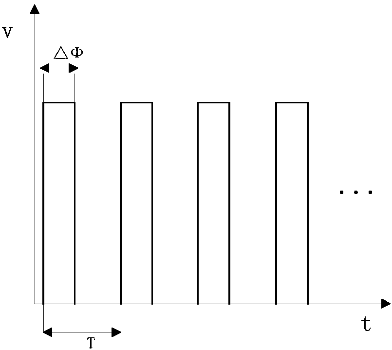
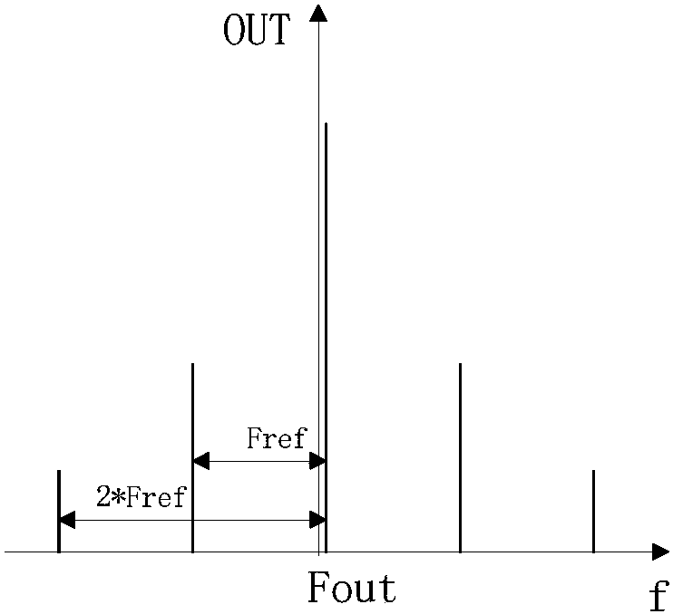
[0034] Embodiments of the present invention will now be described with reference to the drawings, in which like reference numerals represent like elements. As mentioned above, the present invention provides a phase-locked loop circuit. In the low spurious operation mode, the present invention makes the pulse output by the phase-locked loop phase detector circuit through the voltage / pulse width converter and the pulse width / voltage converter The frequency multiplication of the signal reduces the high-frequency component of the control signal at the input terminal of the voltage-controlled oscillator, reduces the stray power of the output signal of the voltage-controlled oscillator, thereby reducing the reference stray of the output signal of the phase-locked loop circuit.

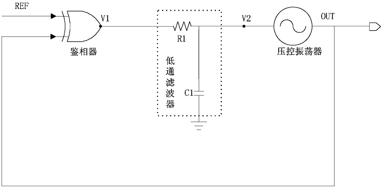
[0035] Please refer to Figure 4 , Figure 4It is a structural diagram of the phase-locked loop circuit of the present invention. As shown in the figure, the phase-locked loop circuit of the present invent...


PUM


Abstract

The invention discloses a phase-locked loop circuit. The circuit comprises a phase discriminator, a low-pass filter and a voltage-controlled oscillator, wherein an external reference clock is input to one input end of the phase discriminator; the output end of the phase discriminator is connected with the input end of the low-pass filter; the output end of the low-pass filter is connected with the input end of the voltage-controlled oscillator; and the output end of the voltage-controlled oscillator is connected with the other input end of the phase discriminator. The circuit further comprises an access selector, a voltage / pulse width converter, a pulse width / voltage converter and a local oscillator, wherein the input end of the access selector is connected with the output end of the phase discriminator; the output end of the access selector is optionally connected with the input end of the low-pass filter or the input end of the pulse width / voltage converter; the output end of the pulse width / voltage converter is connected with the input end of the voltage / pulse width converter; and the output end of the voltage / pulse width converter is connected with the input end of the low-pass filter. According to the phase-locked loop circuit, high-frequency components of a control signal at the input end of the voltage-controlled oscillator are reduced, reference spurs of an output signal of the phase-locked loop circuit are reduced, and the frequency of the output signal is more stable and reliable.

Description

technical field [0001] The invention relates to the field of integrated circuits, in particular to a phase-locked loop circuit. Background technique [0002] Please refer to figure 1 , figure 1 It is the structural diagram of the PLL circuit of the prior art, as shown in the figure, the existing PLL circuit is composed of a phase detector, a low-pass filter (in figure 1 It consists of three parts: resistor R1 and capacitor C1) and a voltage-controlled oscillator. The two input terminals of the phase detector are respectively connected with the output terminal of the phase-locked loop circuit (that is, the output terminal of the voltage-controlled oscillator) and the external reference clock source, and the external reference clock source inputs the reference clock signal generated by it to the discriminator The phase detector converts the difference between the phase Φref of the reference clock source signal REF and the phase Φout of the voltage-controlled oscillator outp...

Claims


Application Information

Patent Timeline
Patent Type & Authority Patents(China)
IPC IPC(8): H03L7/089
CPCH03L7/089
Inventor 何力
Owner IPGOAL MICROELECTRONICS (SICHUAN) CO LTD
Why Eureka
Try Eureka