A Modulation Transfer Function Calculation Method for Spaceborne Camera

A technology for modulating transfer function and spaceborne camera, applied in the field of space optics, can solve problems such as parameter model approximation, and achieve the effects of improved constraints, strong engineering application value, and fast and convenient solution process.

Inactive Publication Date: 2017-07-25
CHANGCHUN INST OF OPTICS FINE MECHANICS & PHYSICS CHINESE ACAD OF SCI
View PDF3 Cites 0 Cited by
  • Summary
  • Abstract
  • Description
  • Claims
  • Application Information

AI Technical Summary

Problems solved by technology

[0005] The present invention provides a modulation transfer function measurement method for space-borne cameras to solve the problem that the existing point light source measurement and calculation modulation transfer function method needs to use parameter model approximation and fitting

Method used


Image

  • A Modulation Transfer Function Calculation Method for Spaceborne Camera
  • A Modulation Transfer Function Calculation Method for Spaceborne Camera
  • A Modulation Transfer Function Calculation Method for Spaceborne Camera

Examples


specific Embodiment approach 1

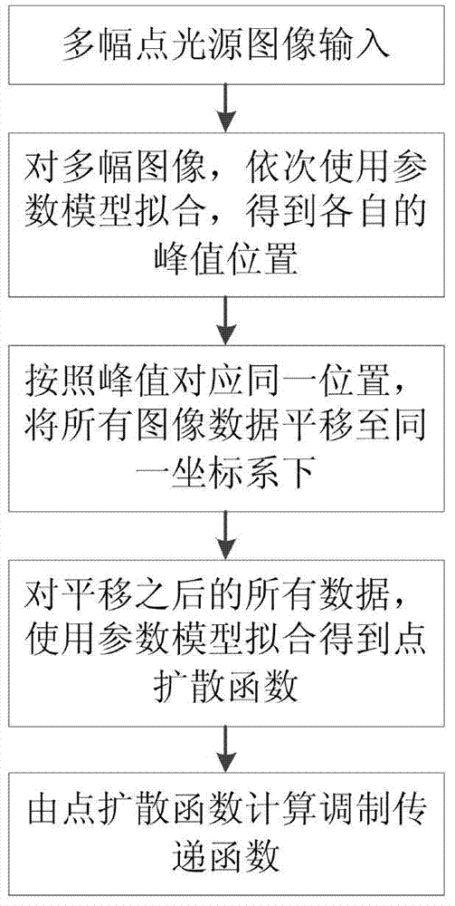
[0017] Specific implementation mode 1. Combination Figure 2 to Figure 5 Description of this embodiment, a method for measuring the modulation transfer function of a spaceborne camera, the method is implemented by the following steps:

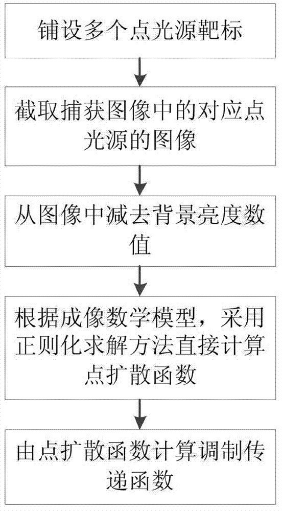
[0018] Step 1. Before the satellite transits, lay a set of convex mirrors with the same specifications in a scene with a consistent background, and the distance between each pair is not less than six ground pixel intervals. The convex mirrors reflect sunlight to form multiple point light source targets. The ground pixel interval is known, but due to the shape of the satellite orbit, the ground pixel interval may vary within a certain range.

[0019] Step 2: From the images captured by the spaceborne camera, corresponding to each point light source, the image data of the same size is intercepted.

[0020] Step 3: Estimating the background brightness of the scene, and subtracting the value of the background brightness from the image data in Step...

specific Embodiment approach 2

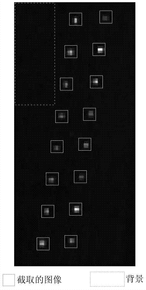
[0043] Specific embodiment two, combine Figure 3 to Figure 5 Illustrate this embodiment, this embodiment is the application of a kind of modulation transfer function measurement method for spaceborne camera described in specific embodiment one to the convex mirror target imaging experiment laid by QuickBirdII, the ground pixel interval of QuickBird can be 0.6m, also can be 0.61-0.72m. The ground pixel interval depends on the pixel size, the focal length of the optical system, and the altitude of the satellite orbit.

[0044] Firstly, the images corresponding to each point light source are intercepted from the captured image, combined with image 3 ,use image 3 The background data in the dotted area in the center calculates the mean value as the background brightness of the whole area, and it is calculated from image 3 Subtract from each point source image of .

[0045] Let λ=0.5 in formula 5, use formula 6 to iterate repeatedly, when the change of h between two adjacent...


PUM


Abstract

A modulation transfer function measurement method for a spaceborne camera relates to the field of space optics technology, and solves the problem that existing point light source measurement modulation transfer function methods need to use parameter models to approximate and fit. First, lay multiple point light source targets before the satellite transits, and then intercept the corresponding point light source image in the captured image. After removing the background brightness value, according to the imaging mathematical model, use the regularization solution method to directly solve the two-dimensional point spread function, and finally Calculate the modulation transfer function from the point spread function. The calculation method of the invention is simple to implement, and the data processing process is simple and accurate, which is of great significance to the evaluation of the imaging quality of the spaceborne camera and has wide application prospects.

Description

technical field [0001] The invention relates to the technical field of space optics, in particular to a method for calculating a point spread function and a modulation transfer function of a spaceborne camera. Background technique [0002] The modulation transfer function of the spaceborne camera is an important indicator for evaluating the quality of the imaging system, which can reflect the clarity of the image to a large extent, so the spaceborne camera has an index requirement for the modulation transfer function, especially the modulation transfer function in Nyquist The value at the frequency. Taking the camera imaging system as a linear shift-invariant system, the point spread function describes the response of the system to the excitation of the point light source, which can characterize the system characteristics. As the normalized modulus of the Fourier transform of the point spread function, the modulation transfer function describes the response of the system to...

Claims


Application Information

Patent Timeline
Patent Type & Authority Patents(China)
IPC IPC(8): G06F19/00G06T7/00
Inventor 郭玲玲任建岳张立国张星祥何斌吴泽鹏
Owner CHANGCHUN INST OF OPTICS FINE MECHANICS & PHYSICS CHINESE ACAD OF SCI
Why Eureka
Try Eureka