
Gas-stripping mud discharging device

A sludge discharge device and air lift technology, applied in the field of water treatment, can solve the problems of stratification of the sludge inlet pipe, high sludge density, low sludge density, etc., and achieve the effect of improving the efficiency of sludge suction.

Active Publication Date: 2014-08-13
ZHEJIANG LIANCHI WATER EQUIP
View PDF8 Cites 7 Cited by
  • Summary
  • Abstract
  • Description
  • Claims
  • Application Information

AI Technical Summary

Problems solved by technology

[0003] During the mud suction process, the sludge discharge device not only sucks away the sludge under the suction bell mouth, but also agitates the sludge around the mud suction bell mouth to a certain extent, causing the clear water in the upper part of the entire sedimentation tank to be muddy. Moreover, after the device starts to work, because the air inlet pipe is far away from the mud suction bell mouth, there is a layering phenomenon on the mud inlet pipe, that is, the air in the mud inlet pipe is located on the upper part of the air inlet pipe due to the thrust of the compressed air. The speed is fast, and the sludge density is small; and the bottom of the sludge inlet pipe has no thrust of compressed air, only suction, resulting in high sludge density, and most of the sludge is difficult to be sucked away

Method used


Image

  • Gas-stripping mud discharging device
  • Gas-stripping mud discharging device
  • Gas-stripping mud discharging device

Examples


Embodiment Construction

[0017] In order to enable those skilled in the art to better understand the solutions of the present invention, the technical solutions in the embodiments of the present invention will be clearly and completely described below in conjunction with the drawings in the embodiments of the present invention.

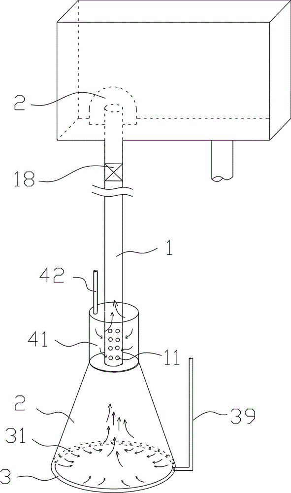
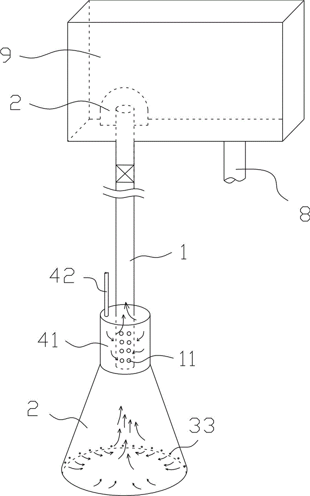
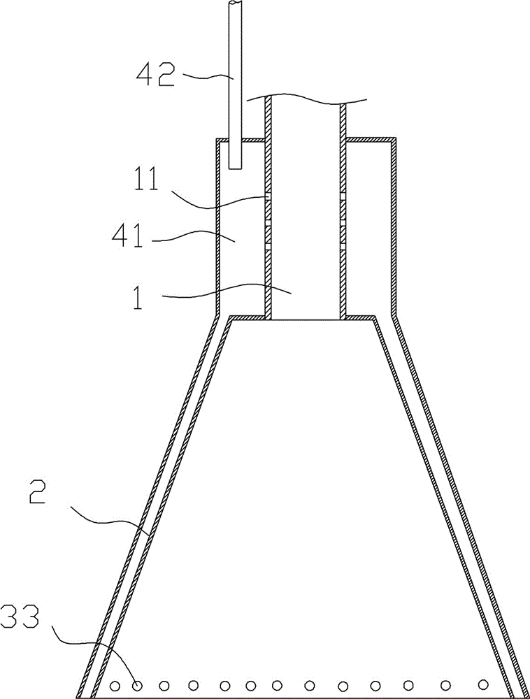
[0018] Such as figure 1 As shown, a kind of air lifting mud discharge device comprises a mud storage tank 9, a mud lifting pipe 1 connected up and down, and an air delivery part for providing compressed air to the inside of the mud lifting pipe 1. The upper end of the mud lifting pipe 1 extends into the storage tank. The inside of the mud tank is connected with the mud storage tank; the upper end of the mud lifting pipe is covered with a mud shield 2, and there is a gap for sludge circulation between the inner wall of the mud shield 2 and the upper end of the mud lifting pipe. The inner wall of the mud shield flows downward into the mud storage tank, preventing the sludge fro...


PUM


Abstract

The invention discloses a gas-stripping mud discharging device. The device comprises a mud storage tank, a through mud-lifting pipe, and a gas-transporting member which is used to provide compressed air to the mud-lifting pipe; the upper end of the mud-lifting pipe is communicated with the mud storage tank, a mud-discharging pipe is arranged in the mud storage tank; a mud-suction cover is arranged on the periphery of the lower part of the mud-lifting pipe, and the lower part of the mud suction cover is provided with a suction assisting part which can eject gas and make gas rise upward. A mud suction cover is provided to cover the lower end part of the mud-lifting pipe, thus an enclosed space is formed for the mud lifting, so during the mud lifting process, sludge on the periphery of the mud suction cover will not be sucked out in a large amount, and thus the settlement tank will not be roiled. Moreover, a suction assisting part is arranged in the mud suction cover, the suction assisting part can carry out impact stirring on the sludge that is covered by the mud suction cover so as to soften the mud, and the softened sludge is easier to suck out. Furthermore, the suction assisting part can form an up-rising air flow in the mud suction cover so as to assist the uprising of sludge, and the mud suction efficiency is improved.

Description

technical field [0001] The invention belongs to the technical field of water treatment, and in particular relates to an air lift and sludge discharge device for sludge. Background technique [0002] Chinese patent CN202139153 discloses an air-lift mud discharge device, which includes an air-lift tank, a mud outlet pipe, a mud inlet pipe, an exhaust pipe, an air intake pipe, a mud suction bell, and a mud suction bell bracket. The mud bell mouth bracket is set on one end of the mud suction bell mouth and fixed on the bottom of the sludge tank. The other end of the mud suction bell mouth is connected to the mud inlet pipe; when working, inject compressed air into the air inlet pipe, and the compressed air drives the mud inlet pipe. The air flows to the gas tank, and the sludge is pumped into the mud inlet pipe and then flows to the gas tank. [0003] During the mud suction process, the sludge discharge device not only sucks away the sludge under the suction bell mouth, but als...

Claims


Application Information

Patent Timeline
Patent Type & Authority Applications(China)
IPC IPC(8): B01D21/24
Inventor 池万青
Owner ZHEJIANG LIANCHI WATER EQUIP
Learn More