Turbine driving rotary spraying device used for assisting in lifting marine drilling platform pile shoe

An offshore drilling platform and turbine technology, which is applied to spray devices, jet devices, valve devices and other directions with movable outlets, can solve the problem that the adsorption of seabed sediment cannot be quickly relieved, the jet flushing area is small, and the rapid jet flushing effect cannot be achieved. and other problems to achieve the effect of shortening the transfer period of the work area, improving the spraying effect, and accelerating the lifting.

Inactive Publication Date: 2014-08-13
齐宝兰
View PDF5 Cites 3 Cited by
  • Summary
  • Abstract
  • Description
  • Claims
  • Application Information

AI Technical Summary

Problems solved by technology

[0002] The direction of the water column ejected by the jetting head of the jetting device in the prior art is fixed, so the action range of the jetting sediment is distributed in a point line, and the jetting area is small, and it is impossible to quickly remove the adsorption of the seabed sediment to the outer surface of the spud can. Can not achieve the best rapid spray boost effect

Method used


Image

  • Turbine driving rotary spraying device used for assisting in lifting marine drilling platform pile shoe
  • Turbine driving rotary spraying device used for assisting in lifting marine drilling platform pile shoe
  • Turbine driving rotary spraying device used for assisting in lifting marine drilling platform pile shoe

Examples


Embodiment

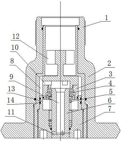
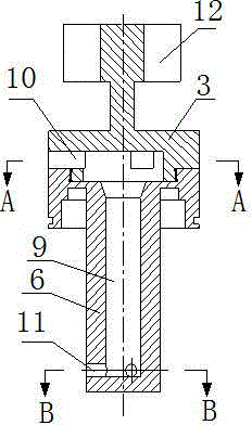
[0017] The working process of the rotary spray flushing device of the present invention is as follows:

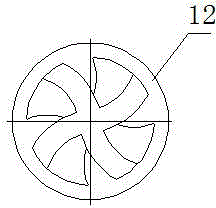
[0018] High-pressure water enters from the interface pipe, pushes the valve core to move down, the valve core moves down in conjunction with the valve stem, the lower end of the valve stem protrudes from the end cap, high-pressure water enters the interface pipe, the impingement turbine drives the valve core to rotate, and then enters the valve cavity through the water inlet hole Enter the blind hole in the center of the valve stem, and then spray out from the spray hole at the lower end of the valve stem along the blind hole. Since the valve core drives the valve stem to rotate, the spray hole rotates to spray water. When the high-pressure water in the mouthpiece is closed, the valve stem As the spool moves up, the injection hole at the lower end of the valve stem retracts upwards into the middle hole of the end cap, the injection hole is closed, and the cleaning operation ...


PUM


Abstract

The invention provides a turbine driving rotary spraying device used for assisting in lifting a marine drilling platform pile shoe. The device comprises a shell, a valve core, a valve rod, an end cover and a reset spring, wherein a valve cavity is formed in the middle of the shell; an interface pipe is arranged on the upper end of the shell; a pipe cavity of the interface pipe is communicated with the valve cavity; the lower end of the valve cavity is connected with the end cover by threads; a through hole is vertically formed in the center of the end cover; the top edge of the valve core is connected with the lower pipe orifice of the interface pipe to form a valve structure; the valve rod is arranged on the lower end of the valve core; a blind hole is formed in the center of the valve rod; a turbine is arranged on the top of the valve core; a water inlet is formed in the middle of the valve core; a water spraying hole is formed in the lower end of the valve rod and is communicated with the water inlet hole by the blind hole; the excircle of the low end of the valve rod penetrates through the vertical through hole in the center of the end cover; the reset spring sleeves the excircle of the low end of the valve rod; the lower end of the reset spring is connected with the upper end of the end cover; the upper end of the reset spring is connected with a thrust bearing at the bottom of the valve core. According to the device, the valve core can automatically rotate in the spraying and flushing process, the point-line spraying and flushing in the prior art are changed into the rotating surface spraying and flushing, the spraying and flushing areas are enlarged, and the spraying and flushing effects are improved.

Description

technical field [0001] The invention relates to the technical field of offshore oil drilling platforms, in particular to a turbine-driven swirling device for lifting boots of offshore drilling platforms. Background technique [0002] The direction of the water column sprayed out by the jetting head of the jetting device in the prior art is fixed, so the action range of the jetting sediment is distributed in a point line, and the jetting area is small, and it is impossible to quickly remove the adsorption of the seabed sediment on the outer surface of the spud can. Can not reach the best rapid spraying and boosting effect. Contents of the invention [0003] The technical task of the present invention is to solve the deficiencies of the prior art, and provide a turbine-driven swirling device for spud shoe lifting of an offshore drilling platform. [0004] The technical solution of the present invention is realized in the following manner. The rotary spray device of the pres...

Claims


Application Information

Patent Timeline
Patent Type & Authority Applications(China)
IPC IPC(8): F16K1/00F16K31/12F16K1/36E02D13/08
CPCB05B3/0409E02B17/0034E02B2017/0078F16K3/262
Inventor 齐宝兰
Owner 齐宝兰
Why Eureka
Try Eureka