Method and device for measuring main shaft rotary errors with capacity of installation eccentricity separation

A technology of rotation error and measuring device, applied in the direction of measuring device, instrument, etc., can solve problems such as complex calculation

Active Publication Date: 2014-08-13
GENERAL ENG RES INST CHINA ACAD OF ENG PHYSICS
View PDF5 Cites 27 Cited by
  • Summary
  • Abstract
  • Description
  • Claims
  • Application Information

AI Technical Summary

Problems solved by technology

These methods have deepened and developed the error separation technology, but there are still deficiencies such as complex calculations.
Moreover, in the measurement of roundness error and spindle rotation error based on the three-point method, ho

Method used


Image

  • Method and device for measuring main shaft rotary errors with capacity of installation eccentricity separation
  • Method and device for measuring main shaft rotary errors with capacity of installation eccentricity separation
  • Method and device for measuring main shaft rotary errors with capacity of installation eccentricity separation

Examples


Embodiment 1

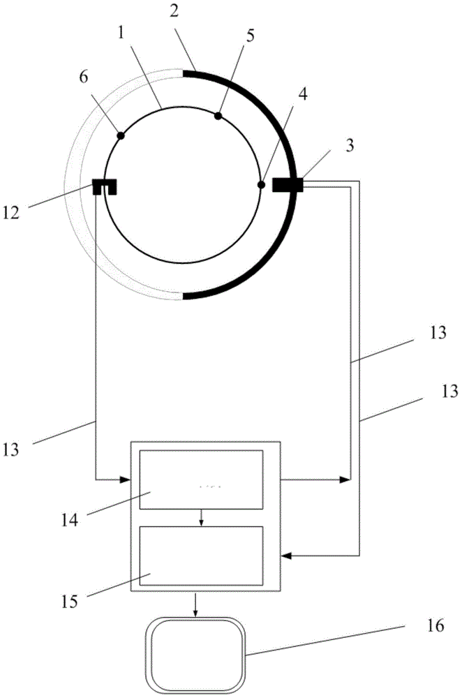
[0047] Such as figure 1 As shown: the displacement sensor (3) is installed on the displacement sensor holder (2), the sensitive axis of the displacement sensor (3) is aligned with the edge of the outer contour of the spindle or the standard ball, after the spindle (1) rotates at a stable speed, the grating encoder (12) is the trigger and positioning signal, the main shaft (1) rotates clockwise for one circle, and the displacement sensor (3) collects N displacement data, denoted as S 0 (θ). Such as figure 2 As shown, the displacement sensor holder (2) and the displacement sensor (3) remain stationary, and the driving spindle (1) is rotated clockwise by an angle α, which is used as the sampling starting point of the displacement sensor (3), and the spindle (1) is clockwise The hour hand rotates one circle, and the displacement sensor (3) collects N displacement data, denoted as S 1 (θ); Displacement sensor holder (2) and displacement sensor (3) remain still, drive the main s...

Embodiment 2

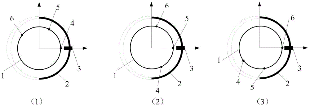
[0062] Such as figure 1As shown: the displacement sensor (3) is installed on the displacement sensor holder (2), the sensitive axis of the displacement sensor (3) is aligned with the edge of the outer contour of the main shaft (1) or the standard ball, after the main shaft (1) rotates at a stable speed, The grating encoder (12) is a trigger and positioning signal, the main shaft (1) rotates one circle clockwise, and the displacement sensor collects N displacement data, denoted as S 0 (θ). Such as image 3 Shown: Rotate the displacement sensor holder (2) clockwise by the angle α, which is the sampling starting point of the displacement sensor (3), the main shaft (1) rotates clockwise for one circle, and the displacement sensor (3) collects N displacement data respectively , denoted as S 1 (θ). Then rotate the displacement sensor holder (2) clockwise by the angle β, and use this as the sampling starting point of the displacement sensor (3), the main shaft (1) rotates clockwi...

Embodiment 3

[0077] Such as figure 1 with Figure 4 As shown: the displacement sensor holder (2) is designed to have three displacement sensor installation holes, and the angles between the three displacement sensor installation positions are designed as follows: the first displacement sensor installation position and the second displacement sensor installation position The included angle between the positions is α, and the included angle between the installation position of the first displacement sensor and the installation position of the third displacement sensor is β. First, the displacement sensor (3) is installed at the position (11) of the holder, and the sensitive axis is aligned with the outer contour edge of the main shaft or the standard ball. After the main shaft (1) rotates at a stable speed, the grating encoder (12) is used as the trigger and positioning signal. The main shaft (1) rotates one circle clockwise, and the displacement sensor (3) collects N displacement data, den...


PUM


Abstract

The invention discloses a method and device for measuring main shaft rotary errors with the capacity of installation eccentricity separation. The device comprises a displacement sensor installation clamping device, a displacement sensor, a grating encoder, a signal cable, a data processor and a computer. According to the measurement process, measurement is conducted by the displacement sensor according to three selectable modes with three different positions of the external profile of a main shaft serving as sampling starting points, other components, except for first-order harmonic waves, of main shaft roundness errors are obtained on the basis of the three-point method principle, secondary separation is conducted according to the provided algorithm, installation eccentricity is separated from the rotary errors, and therefore a pure rotary movement error value of the main shaft is obtained. On one hand, the roundness errors of the profile of the main shaft and eccentric errors of installation of a standard ball and the sensor are separated from the rotary movement errors of the main shaft, so that the separation operand is small. On the other hand, only one displacement sensor is adopted and measurement errors caused by a sensor performance difference because of three sensors adopted in a common three-point method error separation technology are avoided.

Description

technical field [0001] The invention relates to a precision instrument manufacturing measurement method, in particular to a method and device for measuring the rotation error of a main shaft with detachable and eccentric installation. Background technique [0002] High-precision spindles and air bearings are key components of precision equipment such as precision machine tools, precision centrifuges, disk drives, high-precision rotating motors and steam turbines. Many factors that affect the precision of precision machining (such as: processing thermal errors, structural errors, Power transmission chain error, spindle rotation error, etc.), the most direct impact on the part processing error is the spindle rotation motion error, and its accuracy is the key to restricting precision machining and high-precision rotation. As the machining accuracy of machine tools reaches the sub-micron or even nanometer level, the machining error of parts caused by the rotation error of the sp...

Claims


Application Information

Patent Timeline
IPC IPC(8): G01B21/20
Inventor 黎启胜凌明祥李思忠王珏严侠张荣宁菲
Owner GENERAL ENG RES INST CHINA ACAD OF ENG PHYSICS
Why Eureka
Try Eureka