
External-embrace type clamp

A technology of external embrace and fixture, which is applied in the direction of manufacturing tools, workpiece clamping devices, auxiliary devices, etc., can solve the problems of inaccurate workpiece positioning, inconvenient operation, and high manufacturing cost, and achieve stable clamping, convenient operation, and manufacturing low cost effect

Active Publication Date: 2014-08-20
HANS LASER TECH IND GRP CO LTD
View PDF6 Cites 48 Cited by
  • Summary
  • Abstract
  • Description
  • Claims
  • Application Information

AI Technical Summary

Problems solved by technology

Most of the external clamps are multi-jaw fixtures, but most of the existing multi-jaw fixtures need to manually lock the jaws to clamp the workpiece. This kind of fixture is not only inconvenient to operate, but also easily leads to inaccurate positioning of the workpiece
Although there are also some multi-jaw fixtures that clamp and position the workpiece in an automated way, the structure of this type of fixture is complex and the manufacturing cost is high.

Method used


Image

  • External-embrace type clamp
  • External-embrace type clamp
  • External-embrace type clamp

Examples


Embodiment Construction

[0021] In order to make the objectives, technical solutions and advantages of the present invention clearer, the following further describes the present invention in detail with reference to the accompanying drawings and embodiments. It should be understood that the specific embodiments described herein are only used to explain the present invention, but not to limit the present invention.

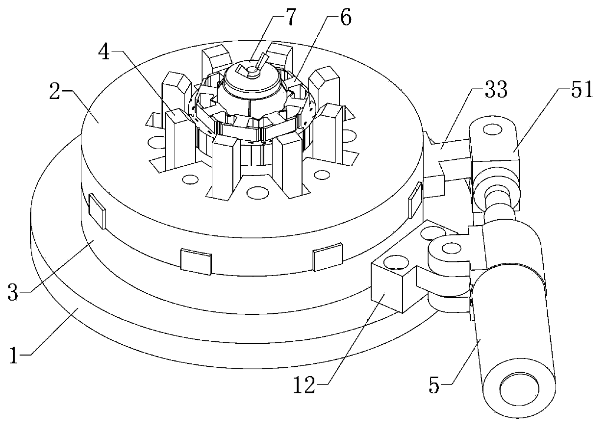
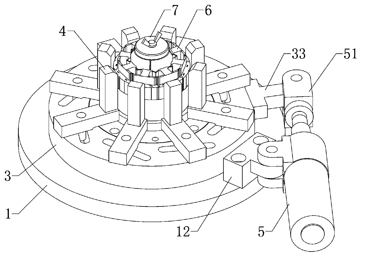
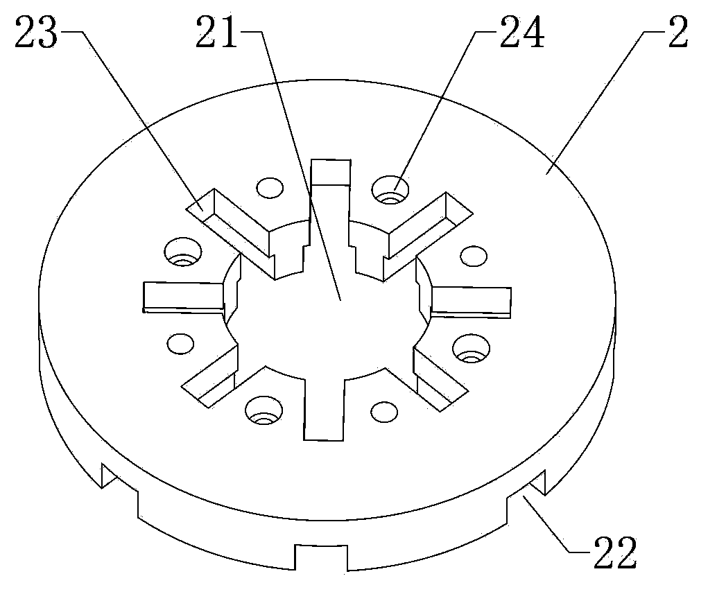
[0022] See figure 1 versus figure 2 , The embodiment of the present invention provides an external holding clamp, including a base 1, a cover 2 stacked on the base 1 and fixedly connected to the base 1, and clamped between the base 1 and the cover Turntable 3 between body 2, see Figure 5 The center of the base 1 is provided with a protruding shaft 11, the center of the protruding shaft 11 is provided with a clamping hole 111 for accommodating the piece 6 to be clamped, and the turntable 3 is sleeved on the protruding shaft 11 and can be moved around. The convex shaft 11 rotates, see image ...


PUM


Abstract

The invention provides an external-embrace type clamp. The external-embrace type clamp comprises a base, a cover body and a rotating disk, wherein the cover body is arranged on the base in a stacking mode and fixedly connected with the base, the rotating disk is clamped between the base and the cover body, a convex shaft is arranged in the center of the base, a clamping hole used for containing a part to be clamped is formed in the center of the convex shaft, the convex shaft is sleeved with the rotating disk, the rotating disk can rotate around the convex shaft, a through hole which can be used for a part to be clamped in the clamping hole to extend out is correspondingly formed in the center of the cover body, a plurality of clamping blocks are evenly arranged on the upper surface of the rotating disk, can rotate reversely along with the rotating disk to close up towards the center of the rotating disk so as to tightly clamp the part to be clamped, and rotate forwardly along with the rotating disk to slide to disperse away from the center of the rotating disk so as to release the part to be clamped, and sliding chutes used for the clamping blocks to slide are correspondingly formed in the cover body. The clamping blocks are provided with sliding shafts, slot holes used for the sliding shafts to slide respectively are evenly formed in the circumference of the surface of the rotating disk in an array mode, and the distance between one end of each slot hole to the center of the rotating disk is shorter than the distance between the other end of the slot hole to the center of the rotating disk. The external-embrace type clamp is small in number of parts, simple in structure, convenient to operate, accurate in location and low in manufacturing cost.

Description

Technical field [0001] The present invention relates to the technical field of clamps, in particular to an external holding clamp. Background technique [0002] In the mechanical manufacturing process, cylindrical workpieces are often fixed and clamped using external holding fixtures. The external holding fixture is a fixture that applies a clamping force to the outer surface of the workpiece. Most of the external holding fixtures are multi-jaw fixtures, but most of the existing multi-jaw fixtures need to manually lock the jaws to clamp the workpiece. This type of fixture is not only inconvenient to operate, but also easily leads to inaccurate positioning of the workpiece. Although some multi-jaw clamps use automated methods to clamp and position the workpiece, the structure of this type of clamp is complex and the manufacturing cost is high. Summary of the invention [0003] The purpose of the present invention is to overcome the defects of the prior art and provide an external...

Claims


Application Information

Patent Timeline
IPC IPC(8): B25B11/00B23K37/04
CPCB23K37/0443
Inventor 曾德东吴志宏高云峰
Owner HANS LASER TECH IND GRP CO LTD
Features
  • Generate Ideas
  • Intellectual Property
  • Life Sciences
  • Materials
  • Tech Scout
  • Unparalleled Data Quality
  • Higher Quality Content
  • 60% Fewer Hallucinations
Learn More