High Voltage Grounding Clamp

A grounding clip, high-voltage technology, applied in the connection, conductive connection, electrical component connection and other directions, can solve the problems of the grounding clip is difficult to hit and hit, the grounding wire is swaying, the sight is not good, etc., to improve safety , Good insulation performance, accurate operation effect

Active Publication Date: 2016-09-21
STATE GRID CORP OF CHINA +1
View PDF6 Cites 1 Cited by
  • Summary
  • Abstract
  • Description
  • Claims
  • Application Information

AI Technical Summary

Problems solved by technology

[0003] Each substation installs more than 300 grounding clips per year; the line voltage level is different, the 110kV line hanging point is about two meters away from the cross arm, and the 220kV line hanging point is more than 3 meters away from the cross arm; the iron tower to be faced There are many kinds of pole towers with different tower shapes, straight towers and tension towers with different hanging points, and corners with different outer corners and inner corners. The most difficult thing to hang the line is the inner corner of the tension tower, especially in the case of large corners. At this time, the hanging point of the grounding wire clip is far away from the operator, and it is difficult for the grounding wire clip to "target" the wire and hit it with one hit, which consumes a lot of physical strength. The installation will be completed with the cooperation of the line tower; the straight tower operation will be affected by factors such as poor line of sight, wind swaying of the ground wire, etc.

Method used


Image

  • High Voltage Grounding Clamp

Examples


Embodiment Construction

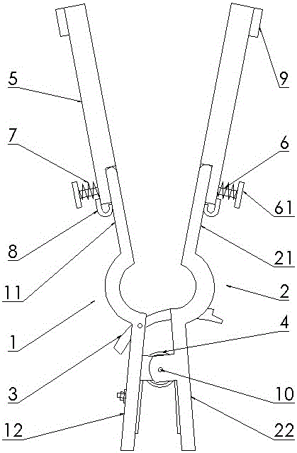
[0021] Below in conjunction with accompanying drawing and embodiment the present invention is described in further detail:

[0022] High voltage grounding clamps such as figure 1 As shown, it includes a left splint 1 and a right splint 2 hinged by a pin shaft 10, and a spring 4 is arranged at the pin shaft 10 to keep the left and right splints in a clamped state. The left splint 1 is divided into two parts by the pin shaft, which are respectively a slightly longer left clamp leaf 11 and a slightly shorter left clamp handle 12 , and the corresponding right clamp plate 2 is divided into a right clamp leaf 21 and a right clamp handle 22 . On the left clamping leaf 11 and the right clamping leaf 21, the positions equidistant from the pin shaft are provided with interlocking arc-shaped slots, and the trigger lever 3 is arranged between the left clamping leaf 11 and the right clamping leaf 21. There is a grounding wire device (the position where the bolt is set in the figure) and a...


PUM


Abstract

The invention discloses a high-voltage grounding wire clamp comprising a left clamping plate and a right clamping plate which are hinged by a pin shaft and respectively composed of a clamping blade and a clamping handle. The outer side face of one end, far away from the pin shaft hinge position, of each clamping blade is hinged with an extension arm through a hinge pin of which the head part is provided with an end cap, the outer cylindrical surface of the hinge pin is sheathed with a compression spring disposed between the end cap of the hinge pin and the outer side face of the extension arm, and the inner side face of the extension arm is flush with the inner side face of the clamping blade when being forwardly hinged in the extension direction of the clamping blade. The position, at which the extension arm is hinged, on each clamping blade is provided with a limiting slot for keeping the extension arm forwardly extended, the limiting slot is an arc metal sheet, one end of the arc of the metal sheet is fixed on the clamping blade, and the other end of the arc correspondingly is in clamped contact with the outer side face of the extension arm. The high-voltage grounding wire clamp of the invention has the advantages of simple structure, convenient operation, and high success rate of operation.

Description

technical field [0001] The invention relates to a grounding wire device used in a substation, in particular to a grounding wire clamp suitable for high-voltage transmission lines. Background technique [0002] After the high-voltage transmission line is powered off, grounding clamps must be mounted on the towers at both ends of the high-voltage transmission line that has been powered off before maintenance or emergency repair operations. The ground wire clamp used at present comprises left clamping plate and right clamping plate, and left clamping plate and right clamping plate are hinged by bearing pin, and pin shaft place is provided with spring, makes left and right clamping plate keep clamping state. The pin shaft divides the splint into two parts, the longer front part of the pin shaft is the clamp leaf, and the shorter rear part of the pin shaft is the clamp handle. Interlocking arc-shaped slots are provided at positions equidistant from the pin shafts on the left and...

Claims


Application Information

Patent Timeline
Patent Type & Authority Patents(China)
IPC IPC(8): H01R11/14
Inventor 王申全高鹏飞秦艳军钱俊国龚自涛刘福祥
Owner STATE GRID CORP OF CHINA
Why Eureka
Try Eureka