Check patentability & draft patents in minutes with Patsnap Eureka AI!

Capacitive pressure sensor with improved electrode structure

An electrode structure, capacitive technology, applied in the direction of measuring fluid pressure through electromagnetic elements, measuring fluid pressure, instruments, etc., can solve problems such as unpredictability and compensation, mechanical lag, etc.

Active Publication Date: 2016-04-27
MKS INSTR INC
View PDF24 Cites 0 Cited by
  • Summary
  • Abstract
  • Description
  • Claims
  • Application Information

AI Technical Summary

Problems solved by technology

Variations in these non-conservative forces cause mechanical hysteresis such that the relative lateral positions of mating components are often non-repeatable and cannot be predicted and compensated for

Method used


Image

  • Capacitive pressure sensor with improved electrode structure
  • Capacitive pressure sensor with improved electrode structure
  • Capacitive pressure sensor with improved electrode structure

Examples


Embodiment Construction

[0041] Exemplary embodiments are now discussed. Other embodiments may additionally or alternatively be used. Obvious or non-essential details may be omitted to save space or for more effective presentation. Rather, some embodiments may be practiced without all of the details disclosed.

[0042] According to one aspect of the invention, a series of slots are introduced into the integrally formed compliant ring, thereby relieving hoop stresses, creating a series of independent flexures which allow a reduction in the radial spring constant at the electrode disc support, while No further reduction in (radial) thickness is required. This effectively reduces the radial spring constant and the maximum possible radial shear load between the electrode disc and sensor housing, while still maintaining the practical usable thickness of the element.

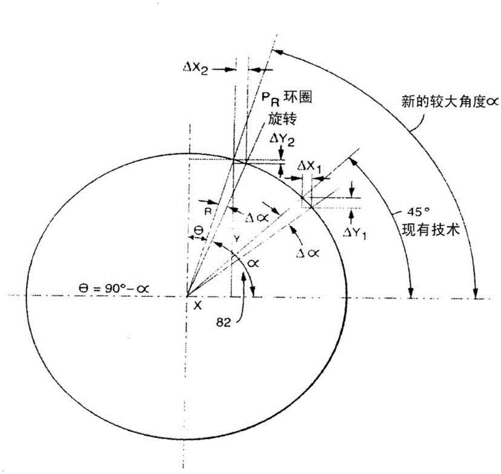
[0043] To accurately measure the lowest pressures, improved control over critical sensor geometries is required. Reduction of the larges...


PUM


Abstract

An improved capacitive manometer comprising: (a) a diaphragm comprising a common electrode; and (b) an electrode structure comprising a center electrode and a ring electrode, wherein the diaphragm is movable relative to the electrode structure (i) the zero position when the pressure on each side of the diaphragm is the same, and (ii) the maximum differential position when the maximum measurable differential pressure is applied to the diaphragm; and the diaphragm support structure, which arranged to support the diaphragm such that the diaphragm is constrained relative to the electrode structure and the common electrode is spaced apart from and aligned with the center electrode and the ring electrode with respect to the alignment axis of the manometer. the ring electrode is axially aligned; and an electrode support structure arranged to support the electrode structure and comprising a compliant ring comprising a ring integrally formed in the ring and surrounding the alignment at least three bends of the axis angularly spaced apart; wherein the electrode support is clamped in place relative to the diaphragm at the location of the bends of the compliance ring.

Description

[0001] Cross References to Related Applications [0002] This application claims the benefit of U.S. Patent Application Serial No. 13 / 248,521, filed September 29, 2011, in the name of Steven D. Blankenship, filed February 1, 2011, entitled "Capacitive Pressure Sensor" Continuation-in-Part of U.S. Patent Serial No. 13 / 018,941 (Attorney Docket No. 086400-0056 (MKS-217)); said application is based upon and claims title filed February 2, 2011 in the name of Steven D. Blankenship Priority to US Provisional Patent Application 61 / 300,620 (Attorney Docket No. 056231-0984 (MKS-217PR)) for "Capacitive Pressure Sensor" and assigned to the present assignee, which is hereby incorporated by reference in its entirety. technical field [0003] The present disclosure relates generally to a capacitive pressure sensor, and more particularly to an improved sensor that provides very precise and accurate pressure measurements, especially at very low (vacuum) pressures. Background technique [00...

Claims


Application Information

Patent Timeline
Patent Type & Authority Patents(China)
IPC IPC(8): G01L9/00G01L19/04
CPCG01L9/0048G01L9/0072G01L19/04
Inventor S·D·布兰肯希普
Owner MKS INSTR INC
Features
  • R&D
  • Intellectual Property
  • Life Sciences
  • Materials
  • Tech Scout
  • Unparalleled Data Quality
  • Higher Quality Content
  • 60% Fewer Hallucinations
Learn More