Pressure sensing implant

a pressure sensing and implant technology, applied in the field of implant packages, can solve the problems of increased link distance, size, cost and manufacturability, additional challenges, etc., and achieve the effects of reducing the size, longevity, and overall performan

Active Publication Date: 2016-11-10
ENDOTRONIX
View PDF8 Cites 29 Cited by
  • Summary
  • Abstract
  • Description
  • Claims
  • Application Information

AI Technical Summary

Benefits of technology

[0010]This application relates to hermetically packaged wireless electronics and more particularly to an implantable sensor d

Problems solved by technology

However, there are many tradeoffs and design constraints in designing such implantable sensors, such as size, cost and manufacturability.
A key challenge in successful commercialization of these implantable wireless sensors is the design tradeoff between implant size and the “link distance”, which is the physical distance between the implant and the external device communicating with or providing energy to the implant.
However, from a wireless communication standpoint, the smaller the implant, the shorter the link distance.
This d

Method used


Image

  • Pressure sensing implant
  • Pressure sensing implant
  • Pressure sensing implant

Examples


Embodiment Construction

[0045]Reference will now be made in detail to embodiments of the invention, examples of which are illustrated in the accompanying drawings. It is to be understood that other embodiments may be utilized and structural and functional changes may be made without departing from the respective scope of the invention.

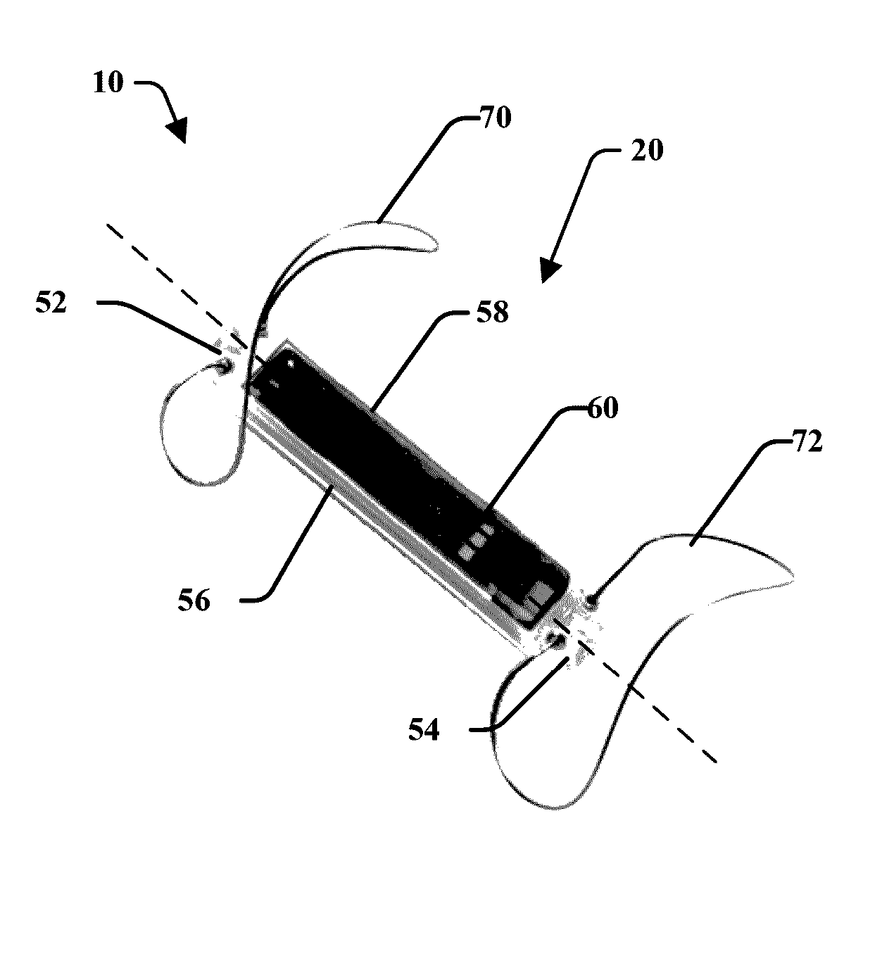
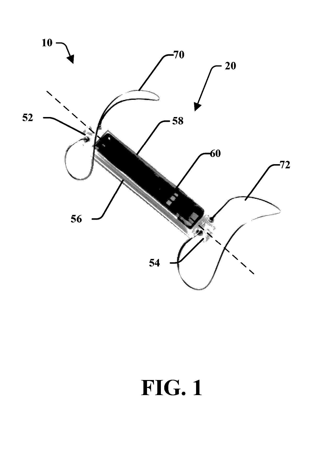
[0046]This application relates to an implant 10 and more particularly to an implantable sensor design and manufacturing approach to optimize manufacturability, size, longevity, RF characteristics, Q, and overall performance. To maximize RF link distance for a given implant size, the implant housing may be constructed to maximize antenna coil area, while still providing ample protection from the environment.

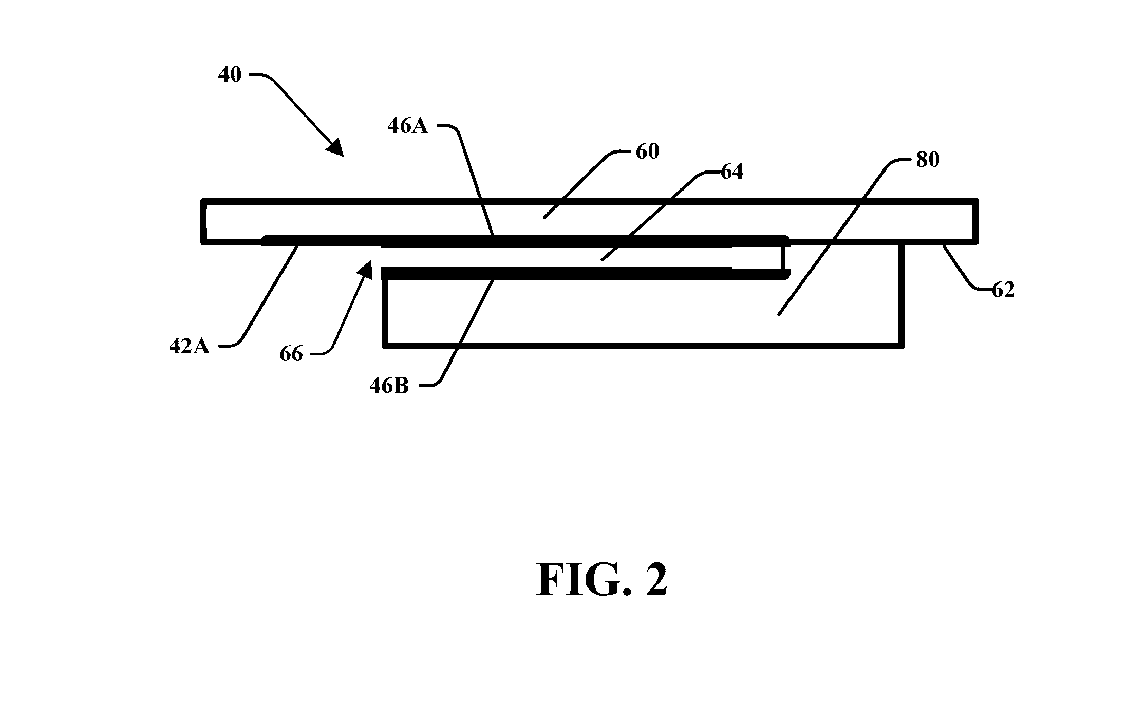
[0047]The implant 10 may include a housing 20 that may utilize thin membrane materials such as glass, quartz, sapphire, fused silica, alumina, titanium, diamond, or other materials, to increase the space available inside an implant package of a fixed outer size. Materials w...


PUM


Abstract

Disclosed is an implant and method of making an implant. The implant having a housing that defines a cavity. The housing includes a sensor comprising a base attached to a diaphragm wherein said base may be positioned within said cavity. The sensor may be a capacitive pressure sensor. The diaphragm may be connected to the housing to hermetically seal said housing. The sensor may include electrical contacts positioned on the diaphragm. The base may define a capacitive gap and a vent wherein the electrodes may be positioned within said capacitive gap such that at least a portion of the electrical contacts extend through the vent. The implant may include a coil in electric communication with the sensor, said coil may be positioned within said housing. A printed circuit board having at least one component may be attached to the floating base.

Description

CROSS-REFERENCE TO RELATED APPLICATIONS[0001]This application is a continuation-in-part of U.S. patent application Ser. No. 14 / 777,654 entitled “PRESSURE SENSING IMPLANT” filed on Sep. 16, 2015 which is a national phase entry application that claims priority to International patent Application No. PCT / US2014 / 030661 filed Mar. 17, 2014 which claims priority to Provisional Patent Application No. 61 / 786,793 entitled “PRESSURE SENSING IMPLANT,” filed on Mar. 15, 2013. This application is also a continuation-in-part of U.S. patent application Ser. No. 14 / 129,725 entitled “IMPLANTABLE SENSOR ENCLOSURE WITH THIN SIDEWALLS,” filed on Feb. 21, 2014, which claims priority to International Patent Application No. PCT / US / 2012 / 044998 entitled “IMPLANTABLE SENSOR ENCLOSURE WITH THIN SIDEWALLS,” filed on Jun. 29,2012 which claims priority to Provisional Patent Application No. 61 / 502,982 entitled “IMPLANTABLE SENSOR ENCLOSURE WITH THIN SIDEWALLS,” filed on Jun. 30, 2011, each of which are hereby inc...

Claims


Application Information

Patent Timeline
IPC IPC(8): A61B5/07A61B5/145A61B5/0215A61B5/03A61B5/00A61B5/01
CPCA61B5/076A61B5/0031A61B5/01A61B2562/168A61B5/0215A61B5/036A61B5/14503A61B5/0059A61B5/6869A61B5/6876A61B5/02152A61B5/08A61B2562/0247
Inventor ROWLAND, HARRYNAGY, MICHAELPLAG, NATHANPANIAN, TYLERSUNDARAM, SURESH
Owner ENDOTRONIX
Why Eureka
Try Eureka