Seat and functional frame thereof

A functional frame and seat technology, applied in the field of functional frames, can solve the problems of increasing the manufacturing cost of the seat, increasing the difficulty of on-site installation and debugging, etc., so as to achieve the effects of improving the comfort of use, avoiding pulling trouser legs, and avoiding pulling.

Inactive Publication Date: 2014-08-27
UE FURNITURE CO LTD
View PDF12 Cites 0 Cited by
  • Summary
  • Abstract
  • Description
  • Claims
  • Application Information

AI Technical Summary

Problems solved by technology

However, in this scheme: the left side link mechanism part, the right side link mechanism part, the connecting rod and the bottom bar are respectively fixedly connected with the two sides of the seat base, and the accuracy of their fixed positions directly determines the left and right sides of the mechanism. Synchronization of motion, as well as the range of motion and stability of the backrest and leg rest, this puts forward a very high requirement for the matching accuracy of the corresponding mounting holes on the seat base, which not only increases the manufacturing cost of the seat, but also greatly increases the Reduced the difficulty of on-site installation and debugging

Method used


Image

  • Seat and functional frame thereof
  • Seat and functional frame thereof
  • Seat and functional frame thereof

Examples


Embodiment 1

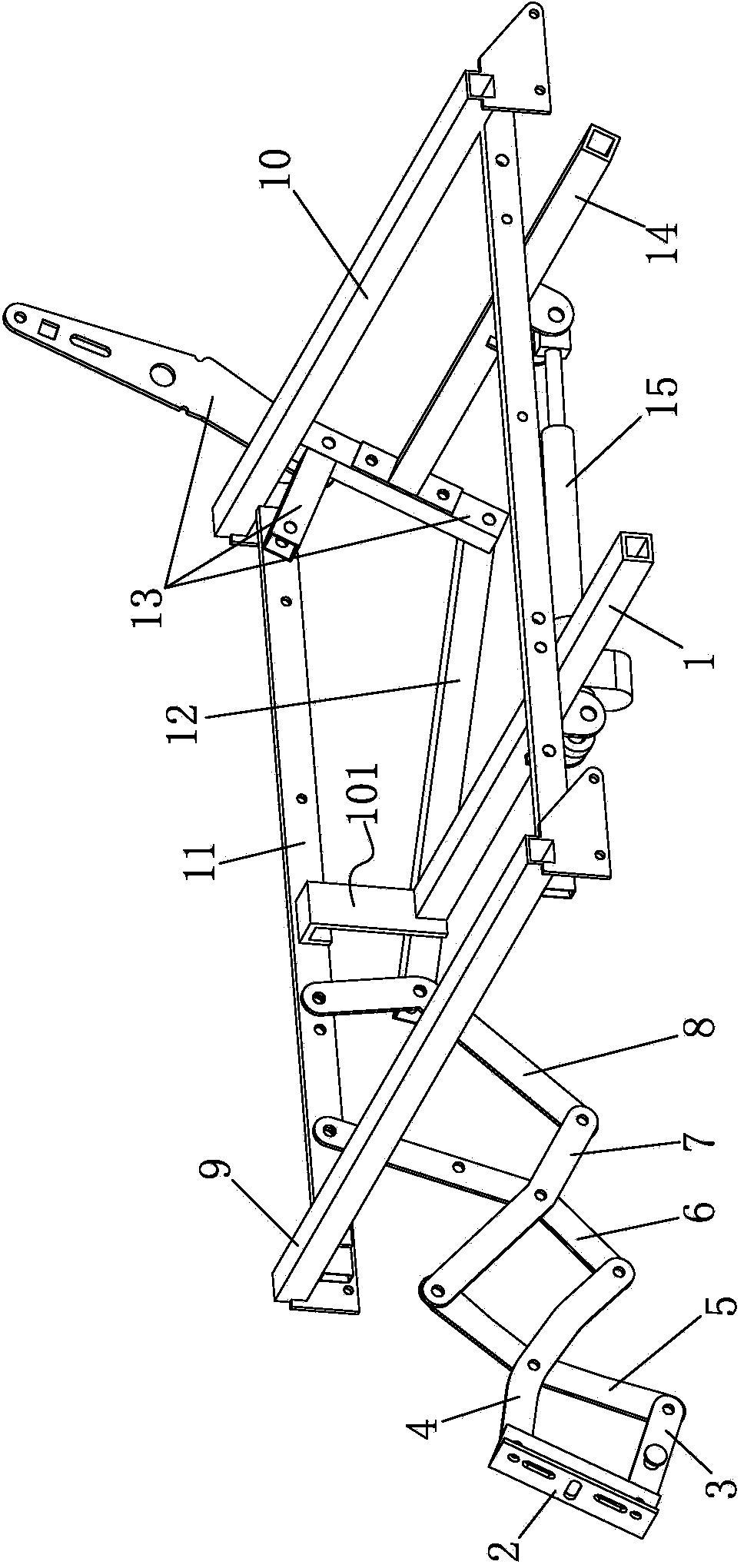
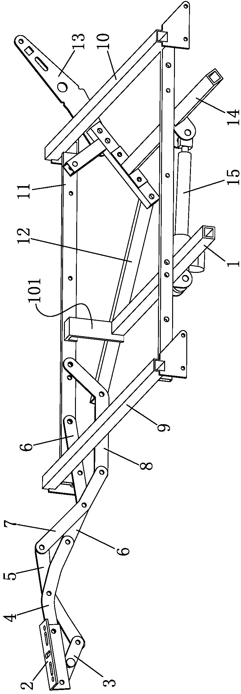
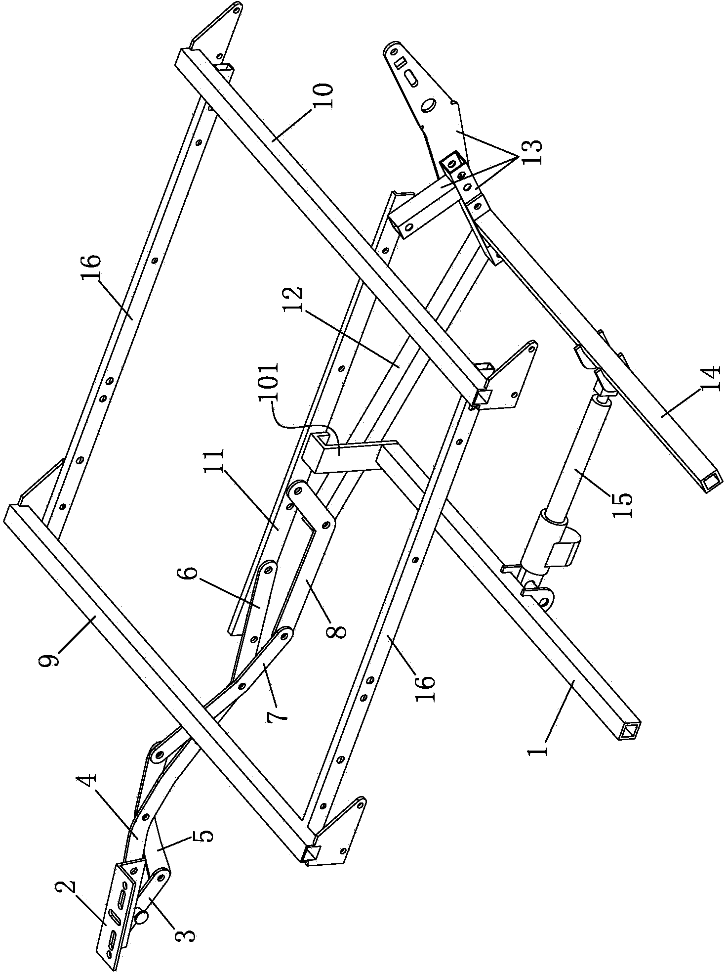
[0024] Such as figure 1 , figure 2 with image 3The functional frame of a seat shown includes a bottom bar 1 and a connecting rod 14 connected by an electric push rod 15. The left and right sides of the bottom bar 1 and the connecting rod 14 are respectively provided with left and right paired leg rests for connection. Frame 2, connecting piece A3, connecting piece B4, connecting piece C5, connecting piece D6, connecting piece E7, connecting piece F8, connecting piece I12, fixing piece 11 and backrest connecting frame 13; one end of said legrest connecting frame 2 One end of the connecting piece A3 is hinged, the other end of the connecting piece A3 is hinged with one end of the connecting piece C5, the other end of the connecting piece C5 is hinged with one end of the connecting piece E7, the other end of the connecting piece E7 is hinged with one end of the connecting piece F8, The other end of the connecting piece F8 is hinged to the front of the fixing piece 11, the oth...


PUM


Abstract

The invention discloses a seat and a functional frame thereof. The functional frame comprises a bottom rod and a connecting rod which are connected with each other through an electric push rod; leg placement plate connecting frames, connecting pieces A, connecting pieces B, connecting pieces C, connecting pieces D, connecting pieces E, connecting pieces F, connecting pieces I, fixing pieces and backrest connecting frames are respectively arranged on the left side and the right side of the bottom rod and the connecting rod in pairs; a leg placement plate is arranged on three four-connecting-rod mechanisms formed by the leg placement plate connecting frames, the connecting pieces A, the connecting pieces B, the connecting pieces C, the connecting pieces D, the connecting pieces E and the connecting pieces F; the electric push rod drives the backrest connecting frames to rotate around the hinge points of the backrest connecting frames and a fixed frame; the rotating force of each backrest connecting frame is transferred to the corresponding connecting piece F through the corresponding connecting piece; the two fixing pieces are fixed to a fixing rod frame in a detachable way; the left end and the right end of the bottom rod are fixedly connected with the two fixing pieces respectively in a detachable way. Due to the adoption of the technical scheme, the functional frame is smooth and stable to move, comfortable to use, reasonable in structure, convenient to transport and assemble and has a space-saving effect.

Description

technical field [0001] The invention belongs to the field of furniture, in particular to a seat such as a recliner, a sofa, etc., and in particular to a functional frame used therein. Background technique [0002] Traditionally, furniture such as lounge chairs, sofas, etc. will be installed with an actuating mechanism - a functional frame, on which a chair frame composed of a backrest, a seat cushion, and a leg rest is installed, and the functional frame is used to realize the movement of the chair frame and the motionless The interconnection between the base components. The functional frame is usually a combination of various mechanical linkages that are operable to provide various comfort features, such as independent reclining movement of the seat assembly, and actuation of the extendable leg rest assembly and associated tipping of the chair frame. While many conventional recliners operate satisfactorily, furniture manufacturers are continually pursuing improved chair f...

Claims


Application Information

Patent Timeline
Patent Type & Authority Applications(China)
IPC IPC(8): A47C1/035A47C4/02
Inventor 季磊
Owner UE FURNITURE CO LTD
Why Eureka
Try Eureka