Multifunctional speed skating shoes blade frame
A speed skating shoe, multi-functional technology, applied to skates, skating, skating boards and other directions, can solve the problems of single structure, far different results, single speed skating function, etc., achieve simple and compact structure, improve speed skating performance, adjust simple effect
- Summary
- Abstract
- Description
- Claims
- Application Information
AI Technical Summary
Problems solved by technology
Method used
Image
Examples
Embodiment 1
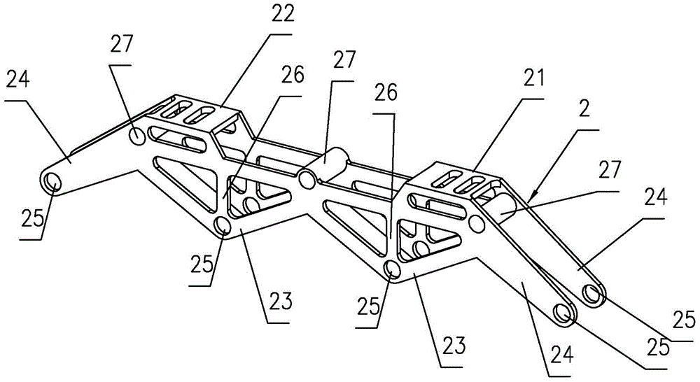
[0027] like figure 2 As shown, it is a multifunctional speed skating shoe knife rest of the present invention, including a knife rest main body 2, and the top of the knife rest main body 2 is provided with a mounting surface, and the mounting surface is a front mounting surface 21 and a rear mounting surface distributed on the front and rear parts thereof. 22. The front mounting surface 21 and the rear mounting surface 22 are located on the same horizontal plane, and pads are selectively installed on the front mounting surface 21 and the rear mounting surface 22 according to the speed skating function to be realized.
[0028] In this embodiment, no pads are provided on the front mounting surface 21 and the rear mounting surface 22 . Realize the first speed skating function: short flat frame, high flexibility, can be used for short distance skating.
[0029] The two side surfaces of the tool holder main body 2 are respectively composed of a pair of inverted isosceles triangul...
Embodiment 2
[0031] like Image 6 As shown, the difference between this embodiment and Embodiment 1 is that: a spacer 3 is provided on the rear mounting surface 22, the spacer 3 is a flat rectangular block, the spacer 3 is detachable, and the spacer 3 The height is 11mm. This embodiment can realize the second speed skating function: common high and low racks, realizing the common knife rest function.
[0032] There are card edges 31, 32 on the bottom edges of the opposite two sides of the spacer 3 respectively, and the pair of card edges 31, 32 form a bayonet. The spacer 3 is located on the rear mounting surface 22, and the rear mounting surface 22 is engaged with the spacer. 3 bayonet. The spacer 3 has an axially penetrating mounting hole 33, and the rear mounting surface 22 has an axially penetrating mounting hole 28. The mounting hole 33 of the spacer 3 is opposite to the mounting hole 28 on the mounting surface 22 for connection. shoe body.
Embodiment 3
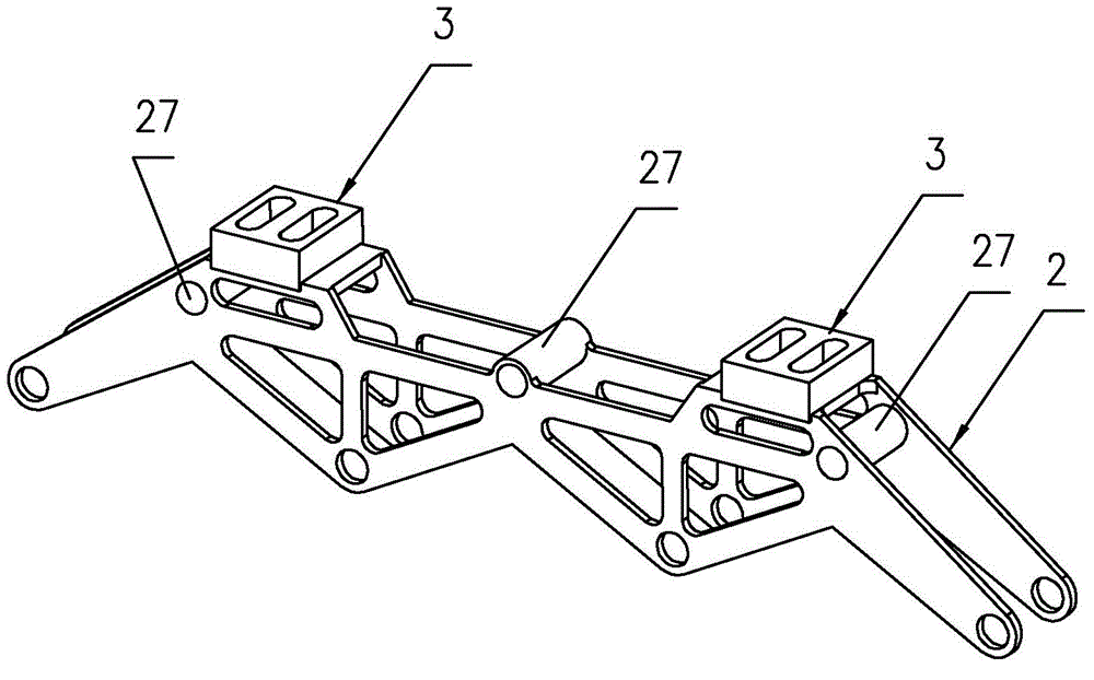
[0034] like Figure 3-5 As shown, the difference between the present embodiment and Embodiment 2 is that spacers 3 are respectively provided on the front mounting surface 21 and the rear mounting surface 22 and the heights of the spacers 3 are the same, and the heights are 11mm. The spacers 3 are Removable installation. This embodiment can realize the third function: a high flat frame, which is suitable for high-speed long-distance taxiing, has strong automatic endurance, and conforms to the physique and physiological characteristics of Asians.
PUM
 Abstract
Description
Claims
Application Information
 - R&D
- Intellectual Property
- Life Sciences
- Materials
- Tech Scout
- Unparalleled Data Quality
- Higher Quality Content
- 60% Fewer Hallucinations
Browse by: Latest US Patents, China's latest patents, Technical Efficacy Thesaurus, Application Domain, Technology Topic, Popular Technical Reports.
© 2025 PatSnap. All rights reserved.Legal|Privacy policy|Modern Slavery Act Transparency Statement|Sitemap|About US| Contact US: help@patsnap.com


