Mistaken-climbing-preventing stopper
A blocker and anti-mis-logging technology, which is applied in the field of blockers and anti-mis-logging blockers, to achieve a good warning effect and increase the scope of use
- Summary
- Abstract
- Description
- Claims
- Application Information
AI Technical Summary
Problems solved by technology
Method used
Image
Examples
Embodiment 1
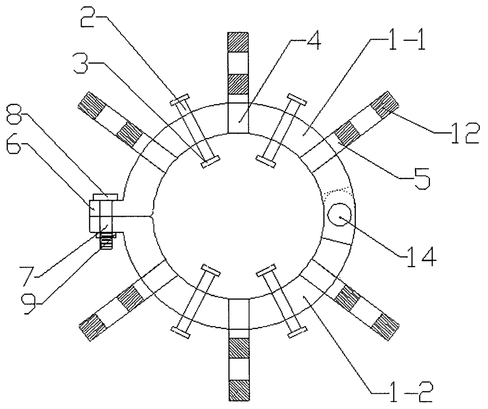
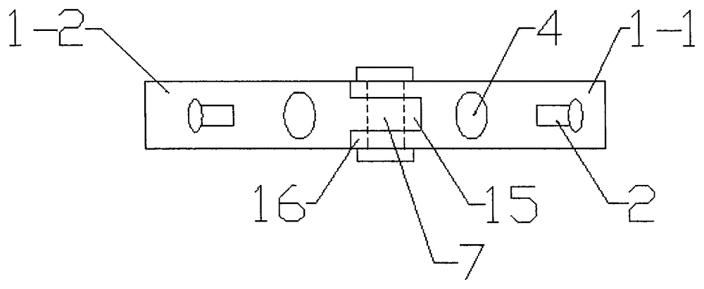
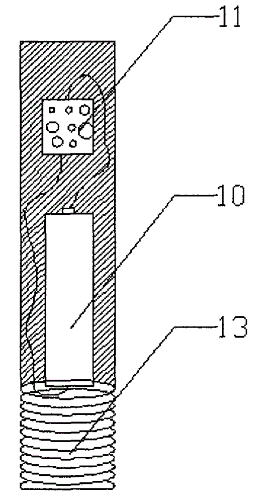
[0017] Such as Figure 1-3 Shown: an anti-mis-entry stopper, including a snap ring 1-1 and a snap ring 1-2, locking bolts 2 are arranged on the left and right sides of the middle position on the outer wall of the snap ring 1-1, and the The fixed end of the locking bolt 2 is provided with an anti-skid iron 3, and the left and right sides and the middle position on the outer wall of the snap ring 1-1 are provided with a fixed hole 4, and the fixed hole 4 is a threaded hole. A warning rod 5 is inserted into the fixed hole 4, and one end of the snap ring 1-1 is provided with a U-shaped groove 16, and the middle position of the U-shaped groove 16 is provided with a positioning hole 7, and the snap ring 1-1 The other end is provided with a connection key 6, and the left and right sides of the middle of the outer wall of the snap ring 1-2 are provided with locking bolts 2, and the fixed end of the locking bolt 2 is provided with an anti-skid iron 3, and the snap ring On the left and...
Embodiment 2
[0020] Such as Figure 1-3 As shown, an anti-mis-entry stopper includes a snap ring 1-1 and a snap ring 1-2. Locking bolts 2 are arranged on the left and right sides of the middle position on the outer wall of the snap ring 1-1. The fixed end of the locking bolt 2 is provided with an anti-skid iron 3, and the left and right sides and the middle position on the outer wall of the snap ring 1-1 are provided with a fixed hole 4, and the fixed hole 4 is a threaded hole. A warning rod 5 is inserted into the fixed hole 4, and one end of the snap ring 1-1 is provided with a U-shaped groove 16, and the middle position of the U-shaped groove 16 is provided with a positioning hole 7, and the snap ring 1-1 The other end is provided with a connection key 6, and the left and right sides of the middle of the outer wall of the snap ring 1-2 are provided with locking bolts 2, and the fixed end of the locking bolt 2 is provided with an anti-skid iron 3, and the snap ring On the left and right ...
PUM
 Abstract
Description
Claims
Application Information
 - R&D
- Intellectual Property
- Life Sciences
- Materials
- Tech Scout
- Unparalleled Data Quality
- Higher Quality Content
- 60% Fewer Hallucinations
Browse by: Latest US Patents, China's latest patents, Technical Efficacy Thesaurus, Application Domain, Technology Topic, Popular Technical Reports.
© 2025 PatSnap. All rights reserved.Legal|Privacy policy|Modern Slavery Act Transparency Statement|Sitemap|About US| Contact US: help@patsnap.com


