Booster type electronic control hydraulic bridge plug feeding tool

An electronically controlled hydraulic and bridge plug technology, applied in wellbore/well parts, earthwork drilling and production, etc., can solve the problems of short service life, long operation time, low work efficiency, etc., and achieve safe and reliable working process and simple maintenance , high work efficiency

Inactive Publication Date: 2014-09-03
JILIN UNIV
View PDF4 Cites 12 Cited by
  • Summary
  • Abstract
  • Description
  • Claims
  • Application Information

AI Technical Summary

Problems solved by technology

[0003] The above-mentioned cable transmission explosive setting method is easy to operate and widely used, but gunpowder is dangerous goods, and the procedures in the process of ordering, storage, and filling are complicated, and accidents are prone to occur in the process of transportation and use. Similar accidents occur from time to time. Sometimes Entry and exit will also be restricted; and the residue after the gunpowder burns is inconvenient to clean up, which affects the repeated use cycle and maintenance workload of the installation tool; in addition, the gunpowder explodes rapidly, the expansion force is large, the load of the installation tool itself is large, and it is easy to deform , so its service life is short and the cost of use is high
Relatively speaking, the hydraulic setting method is safe and reliable, but the operation time is long and the work efficiency is low

Method used


Image

  • Booster type electronic control hydraulic bridge plug feeding tool

Examples


Embodiment Construction

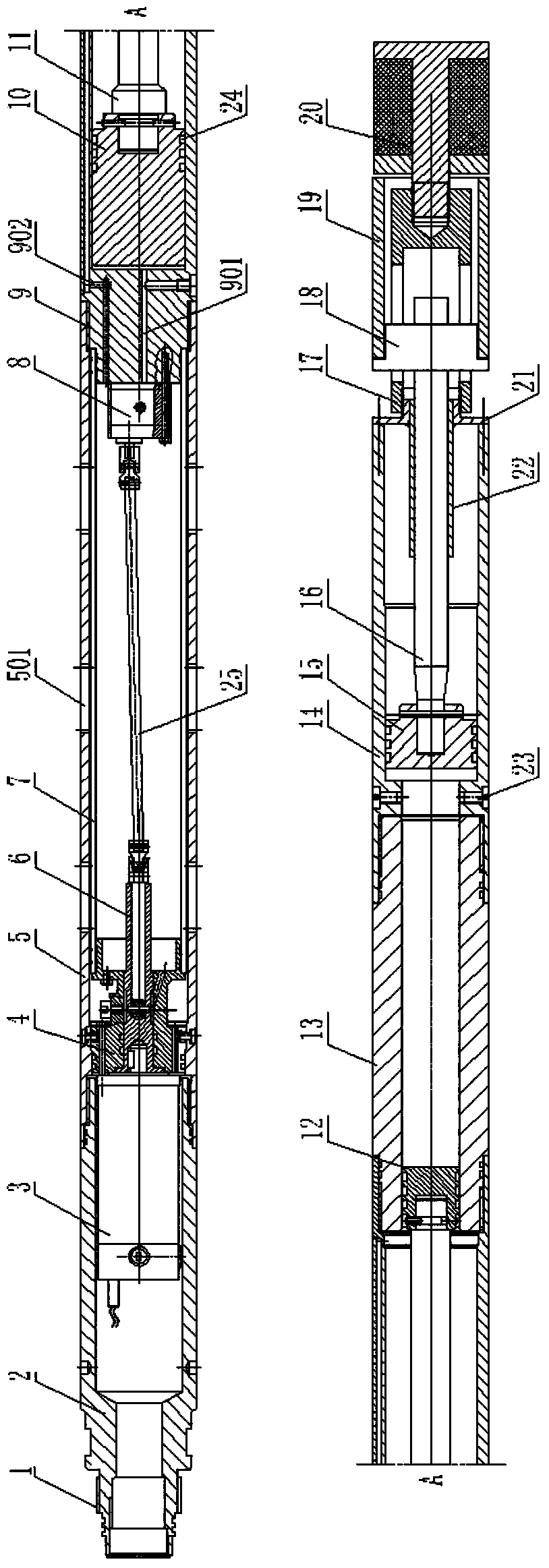
[0022] Such as figure 1 As shown, the pressurized electronically controlled hydraulic bridge plug insertion tool includes a motor cylinder 2, a balance cylinder 5, a hydraulic pressure boosting system and a working cylinder which are threaded sequentially from top to bottom. A connecting plug 1 integrated with the motor barrel 2 is provided at the upper end of the motor barrel 2, and a motor 3 is arranged in the motor barrel 2. As preferably, the motor 3 is a rare-earth DC motor, and the motor 3 wires are drawn from the upper end of the motor barrel 2. A motor base 4 is fixed on the inner upper part of the balance cylinder 5 by screws, and the motor 3 is fixed on the upper end of the motor base 4 by bolts. A transmission shaft 6 runs through the inner hole of the motor base 4 , and the upper end of the transmission shaft 6 is keyed to the output shaft of the motor 3 . A plurality of ventilation slots 501 are symmetrically provided on the cylinder wall of the balance cylinder ...


PUM


Abstract

The invention discloses a booster type electronic control hydraulic bridge plug feeding tool. The tool comprises a motor barrel, a balance barrel, a hydraulic boosting system and a working cylinder, wherein the motor barrel, the balance barrel, the hydraulic boosting system and the working cylinder are sequentially connected from top to bottom. A motor is arranged in the motor barrel, an oil storage chamber and an oil pump are arranged in the balance barrel, and the oil pump and an output shaft of the motor are in drive connection. The hydraulic boosting system is used for increasing output pressure of the small-power oil pump to pressure required by setting of a bridge plug. The working cylinder acts on the bridge plug through a bridge plug connecting assembly, and setting is achieved. The working process is safe and reliable, the pressure of the working cylinder can quickly reach 50 MPa, the requirements for bridge plug installation setting force are quickly met, operation time is shot, and working efficiency is high. The tool can be pulled out of a well mouth along with an oil pipe after setting of the bridge plug, the hydraulic boosting system is controlled to reset and then can be reused, the service life is long, and maintenance work is simple. The working process of the hydraulic system is controllable, the magnitude of loads and the loading speed can be adjusted according to requirements, ground monitoring can be achieved, and the installation process of the bridge plug can be grasped in real time.

Description

technical field [0001] The invention belongs to downhole plugging equipment, in particular to a pressurized electronically controlled hydraulic bridge plug delivery tool. Background technique [0002] At present, the commonly used bridge plug setting is mainly divided into two forms: oil pipe transmission hydraulic setting and cable transmission explosive setting. When the oil pipe transfers the bridge plug to set, pressurize the oil pipe to push the piston to compress the rubber pipe, push the slips and the rubber pipe in place at the same time, continue to pressurize, break the tension rod, and release the bridge plug to realize the setting. The setting tool starts with the oil pipe. Out of the wellhead; when the cable transmission bridge plug is set, the explosive energy generated by the igniter detonating the gunpowder through the cable is connected to push the piston, and the piston pushes the extrusion cylinder to open the slips, compress the rubber hose, and then pull...

Claims


Application Information

Patent Timeline
Patent Type & Authority Applications(China)
IPC IPC(8): E21B23/06E21B23/10
Inventor 卢延辉高长军张友坤刘明树马肖
Owner JILIN UNIV
Why Eureka
Try Eureka