Nozzle presetter for laser machining tool of laser beam machine

a laser beam machine and laser beam technology, which is applied in the direction of manufacturing tools, metal-working equipment, welding equipment, etc., can solve the problems of lowering the transmittance of the laser beam, reducing the accuracy of machining, and reducing the flexibility of operations, so as to increase the flexibility of operations and work safely. , the effect of not burdening the operator

Inactive Publication Date: 2008-03-18
YAMAZAKI MAZAK KK
View PDF18 Cites 17 Cited by
  • Summary
  • Abstract
  • Description
  • Claims
  • Application Information

AI Technical Summary

Benefits of technology

[0021]According to the present invention, since the operation of centering the nozzle with the optical axis can be performed in advance outside the laser beam machine, there is no need to interrupt a machining operation. This greatly improves productivity.
[0022]Since laser machining tools can be set up outside the machine, machining can be performed immediately after exchanging laser machining tools between the laser beam machine and nozzle presetter. This greatly improves productivity.
[0023]Since the required quantity of machining tools can be set up in advance, it is possible to respond quickly to changes in machined material and workpiece thickness. This greatly improves productivity in single-article multi-product production.
[0024]Since machining tools can be set up in advance, it is possible to use an automatic tool changer, enabling long, unattended operation.
[0026]The use of a safe low-power alternative light source allows the operator to work safely.
[0027]Since the nozzle presetter is of a tabletop type which can be moved manually, it increases flexibility of operations and does not unduly burden the operator.

Problems solved by technology

Since the machining lens is located near the workpiece, being exposed to workpiece vapor, molten particles, and other contaminants produced in its installation environment, it can always get contaminated with dirt, which lowers its transmittance, causing heat of the laser beam to build up in the machining lens.
Consequently, geometry of the machining lens is changed, lowering machining accuracy and even resulting in breakage of the machining lens or otherwise disabling machining.
However, the geometry of the machining lens contains a significant degree of inaccuracy for manufacturing reasons and thus, the center of the optical axis does not coincide with the nozzle center.
Since the operation of centering the nozzle with the optical axis must be performed on the machine, machining must be stopped temporarily, resulting in reduced productivity.
Besides, it requires skill to center the nozzle sufficiently with the burn mark left on the target.
It is not possible to predict when a machining lens needs replacement due to its failure.
This makes it impossible to accomplish long, unattended operation.
Thus, an operation which requires the operator to bring his / her eyes close to the nozzle involves danger.

Method used


Image

  • Nozzle presetter for laser machining tool of laser beam machine
  • Nozzle presetter for laser machining tool of laser beam machine
  • Nozzle presetter for laser machining tool of laser beam machine

Examples


Embodiment Construction

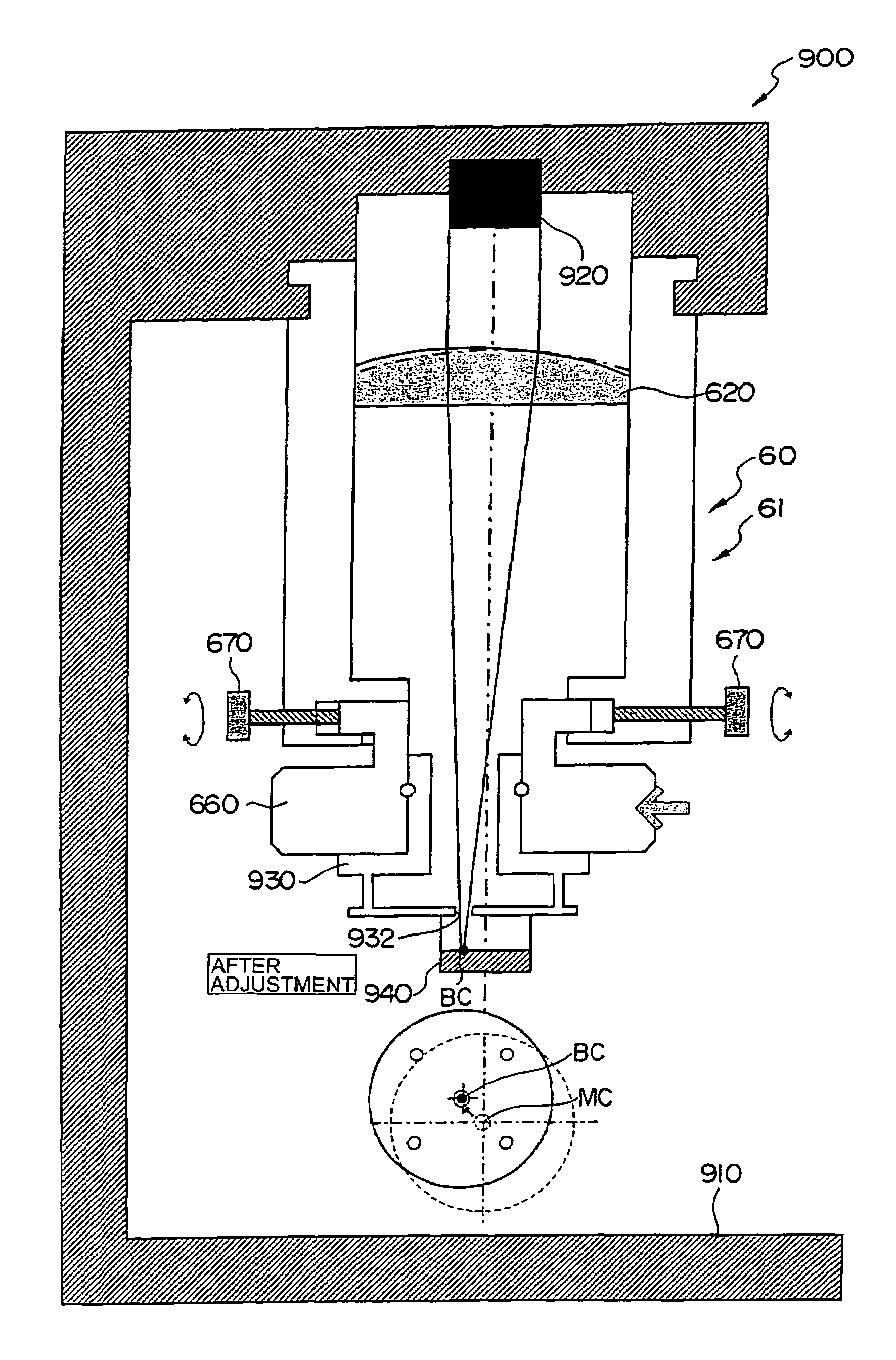
[0042]The present invention provides a nozzle presetter for laser machining tools used on the laser beam machine.

[0043]FIG. 8 is an explanatory diagram illustrating a principle of focal position adjustment on the laser beam machine.

[0044]The laser machining tool 60 mounted on the machining head 50 consists of a torch member 61 and nozzle member 65.

[0045]The torch member 61 has a torch member body 610 and contains a machining lens 620.

[0046]A nozzle mounting member 660 is attached to the tip of the torch member 61 and screwed into the torch member body 610. Four adjustment screws 670 allow axial position to be adjusted. The nozzle member 65 is mounted on the nozzle mounting member 660. The nozzle member 65 has a nozzle hole 652 in its body 650 and is attached and detached to / from the nozzle mounting member 660 via mounting means 654.

[0047]A laser beam collected by a machining lens 620 forms a focus BC. Desirably the focus BC coincides with the machine center MC of the laser beam mach...


PUM

PropertyMeasurementUnit
output voltageaaaaaaaaaa
diameteraaaaaaaaaa
flow velocityaaaaaaaaaa

Abstract

The invention provides a nozzle presetter for laser machining tool of laser beam machine for externally making position adjustments of nozzles for laser machining tools mounted on a laser beam machine.A nozzle presetter 900 has a base 910, and a support portion 912 is mounted on an upper part of the base 910 to removably support a laser machining tool 60. An alternative beam source 920 is mounted at the center position in an upper part of the support portion 912. A target member 930 is removably mounted on a nozzle mounting member 660 of the laser machining tool 60 via mounting means 654. The target member 930 has a photoreceptor 940 mounted just under a center hole 932. The photoreceptor. 940 senses the quantity of light reaching the photoreceptor through the center hole 932 of the target member 930. The operator changes the axial position of the nozzle mounting member 660 using four adjustment screws 670. When a collected beam passes through the center hole 932 of the target member 930, output voltage of the photoreceptor 940 rises. When the operator is notified to that effect, he / she completes the adjustment.

Description

[0001]The present application is based on and claims priority of Japanese patent application No. 2004-155948 filed on May 26, 2004, the entire contents of which are hereby incorporated by reference.BACKGROUND OF THE INVENTION[0002]1. Field of the Invention[0003]The present invention relates to a nozzle presetter for a laser machining tool of a laser beam machine, capable of making adjustments outside the laser beam machine in advance so that the center of an optical axis narrowed by a machining lens will coincide with the center of a nozzle in the machining tool to be replaceably mounted on the laser beam machine, and thereby improving productivity and safety of the laser beam machine.[0004]2. Description of the Related Art[0005]Conventionally, a laser beam machine leads a laser beam outputted from a laser oscillator device to a machining lens, focuses it onto the focal position of the machining lens, and machining a workpiece placed near the focal position of the machining lens thr...

Claims


Application Information

Patent Timeline
Patent Type & Authority Patents(United States)
IPC IPC(8): B23K26/04B23K26/06B23K26/042B23K26/064
CPCB23K26/04B23K26/041B23K26/043B23K26/1494B23K26/1482B23K26/042
Inventor YAMAZAKI, TSUNEHIKOMIYAKAWA, NAOOMI
Owner YAMAZAKI MAZAK KK
Why Eureka
Try Eureka