Rotor

A rotor and rotor body technology, applied in the field of rotors, can solve the problems of easy growth, reduced motor durability, and easy looseness, etc., and achieve the effect of compact design, long service life, and not easy to shift

Active Publication Date: 2014-09-03
TONGLING HEWU MACHINERY MFG
View PDF5 Cites 0 Cited by
  • Summary
  • Abstract
  • Description
  • Claims
  • Application Information

AI Technical Summary

Problems solved by technology

During the operation of the existing motor rotor, the permanent magnet is easy to shift or break away from the rotor body, which shortens the service life of the rotation, and at the same time, it is difficult for the motor to work for a long time, which reduces the durability of the motor
Although the existing patent No. CN203278437U adopts some technical means to strengthen the fixing of the permanent magnet in the rotor body, it adopts some conventional reinforcement methods, and most of them use some connectors to strengthen the connection. It is cumbersome, easy to grow and loose, and the overall effect is not ideal when used

Method used


Image

  • Rotor

Examples


Embodiment Construction

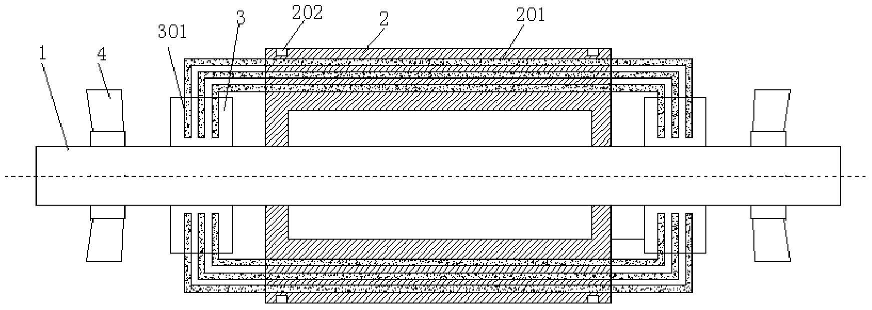
[0011] Referring to the drawings, a rotor includes a rotating shaft 1, a rotor body 2 and a permanent magnet 3. The rotating shaft 1 is fixedly connected to the rotor body 2. The rotor body 2 is provided with a plurality of permanent magnet placement slots 201. The positions on both sides of the rotor body 2 The rotating shaft is provided with a fixed disk 3, and the fixed disk is provided with a plurality of permanent magnet fixing slots 301. The permanent magnet 3 is elongated, with two fixed parts extending outward, and the elongated part is embedded in the placement groove of the rotor body. Inside, the fixed part is set in the slot of the fixed plate, so that the structural shape is equivalent to firmly fixing the permanent magnet and the rotor body together, and positioning the permanent magnet horizontally and vertically. Both ends of the rotor body are equipped with fixed The ring 202 further strengthens the permanent magnet and fixes it on the rotor body, and has a com...


PUM


Abstract

The invention discloses a rotor. The rotor comprises a rotation shaft, a rotor body and permanent magnets, wherein the rotation shaft is fixedly connected with the rotor body, the rotor body is provided with multiple permanent magnet displacing grooves, a fixing disc is arranged on the rotation shaft at two side positions of the rotor body, the fixing disc is provided with multiple permanent magnet fixing slots, the permanent magnets are long-strip structures, the two permanent magnets have fixed portions extending outwards, the long-strip portions are embedded in rotor body displacing grooves, and the fixed portions are arranged in the fixing disc slots. The rotor solves disadvantages in the prior art and has a compact design structure, the permanent magnets are fixed and secure, deviation is not liable to occur, and service life is long.

Description

technical field [0001] The invention relates to the technical field of motor components, in particular to a rotor. Background technique [0002] The motor is a conversion device used to realize electrical energy and mechanical energy and mechanical energy and electrical energy. The motor rotor is a rotating part in the motor and is a consumable part. During the operation of the existing motor rotor, the permanent magnet is easily displaced or separated from the rotor body, which shortens the service life of the rotation. At the same time, it is difficult for the motor to work for a long time, which reduces the durability of the motor. Although the existing patent No. CN203278437U adopts some technical means to strengthen the fixing of the permanent magnet in the rotor body, it adopts some conventional reinforcement methods, and most of them use some connectors to strengthen the connection. It is cumbersome, easy to grow and loose, and the overall effect is not ideal when us...

Claims


Application Information

Patent Timeline
Patent Type & Authority Applications(China)
IPC IPC(8): H02K1/27
Inventor 张勇
Owner TONGLING HEWU MACHINERY MFG
Why Eureka
Try Eureka