Vibration-damping band for substituting speed hump to reduce floor slab vibration
A technology of vibration reduction belt and deceleration belt, which is applied in the field of vibration reduction belt, can solve the problems that the floor vibration acceleration does not meet the requirements of building comfort, the structure does not meet the comfort level, etc., and achieves simple structure, easy installation and replacement, and construction convenient effect
- Summary
- Abstract
- Description
- Claims
- Application Information
AI Technical Summary
Problems solved by technology
Method used
Image

Examples
Embodiment Construction
[0018] The present invention will be further described below in conjunction with the accompanying drawings and specific embodiments.
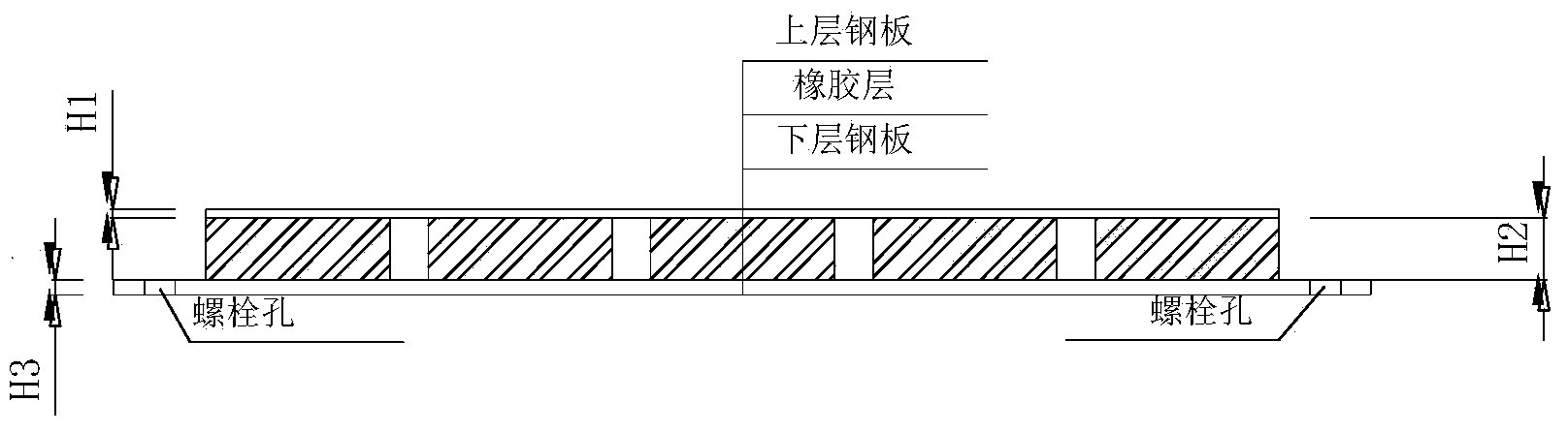
[0019] as attached figure 1 As shown, the vibration reduction of this method to replace the speed bump to reduce the vibration of the floor is divided into 3 layers, the upper layer and the lower layer are steel plates, and the middle layer is soft rubber with buffering effect; the overall height of the vibration reduction belt is lower than the speed bump. The height of the upper steel plate is H1, the height of the middle layer is H2, and the height of the lower steel plate is H3. The height of the deceleration belt can affect the impact load on the floor when the vehicle passes the deceleration belt, that is, the higher the height, the greater the load generated when the vehicle passes the deceleration belt, and the greater the floor vibration caused, so control the vibration reduction belt. The height can effectively control the vibration ...
PUM
 Abstract
Description
Claims
Application Information
 - Generate Ideas
- Intellectual Property
- Life Sciences
- Materials
- Tech Scout
- Unparalleled Data Quality
- Higher Quality Content
- 60% Fewer Hallucinations
Browse by: Latest US Patents, China's latest patents, Technical Efficacy Thesaurus, Application Domain, Technology Topic, Popular Technical Reports.
© 2025 PatSnap. All rights reserved.Legal|Privacy policy|Modern Slavery Act Transparency Statement|Sitemap|About US| Contact US: help@patsnap.com