Ground marking device and process and installation comprising same

a technology of ground markings and process elements, applied in process and machine control, optical radiation measurement, instruments, etc., can solve the problems of undesirable or prohibited remote control by radio waves, difficult to control beacons installed to be installed in group mode, etc., and achieve the effect of convenient installation or replacemen

Inactive Publication Date: 2005-11-03
SCHNEIDER ELECTRIC IND SAS
View PDF22 Cites 15 Cited by
  • Summary
  • Abstract
  • Description
  • Claims
  • Application Information

AI Technical Summary

Benefits of technology

[0007] The object of the invention is to provide a ground marking device able to be easily installed or replaced and/or ha...

Problems solved by technology

For example, it is difficult for beacons installed to be controlled in group mode to be controlled in sequential mode or in individual mode by remote control withou...

Method used


Image

  • Ground marking device and process and installation comprising same
  • Ground marking device and process and installation comprising same
  • Ground marking device and process and installation comprising same

Examples


Embodiment Construction

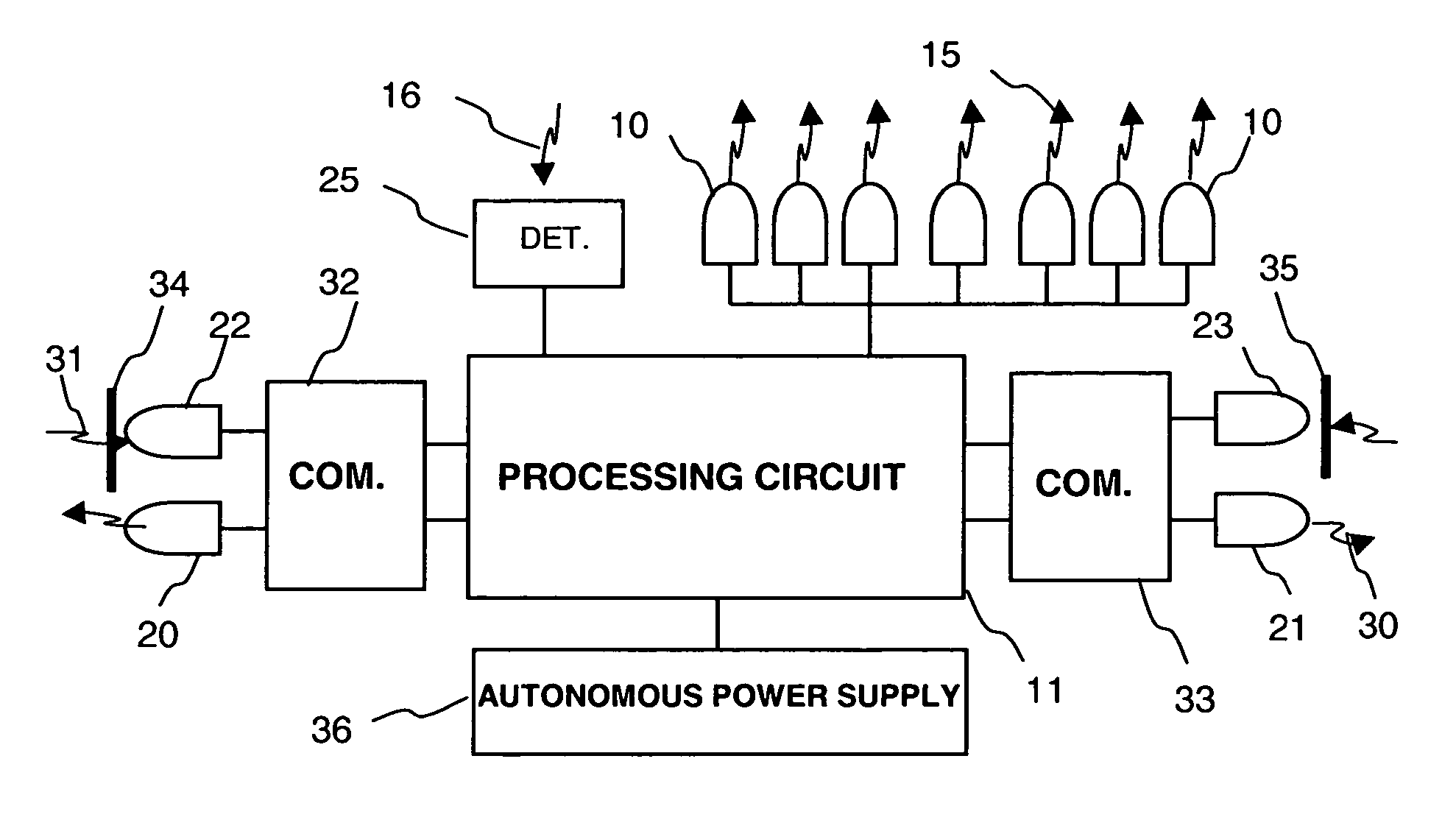
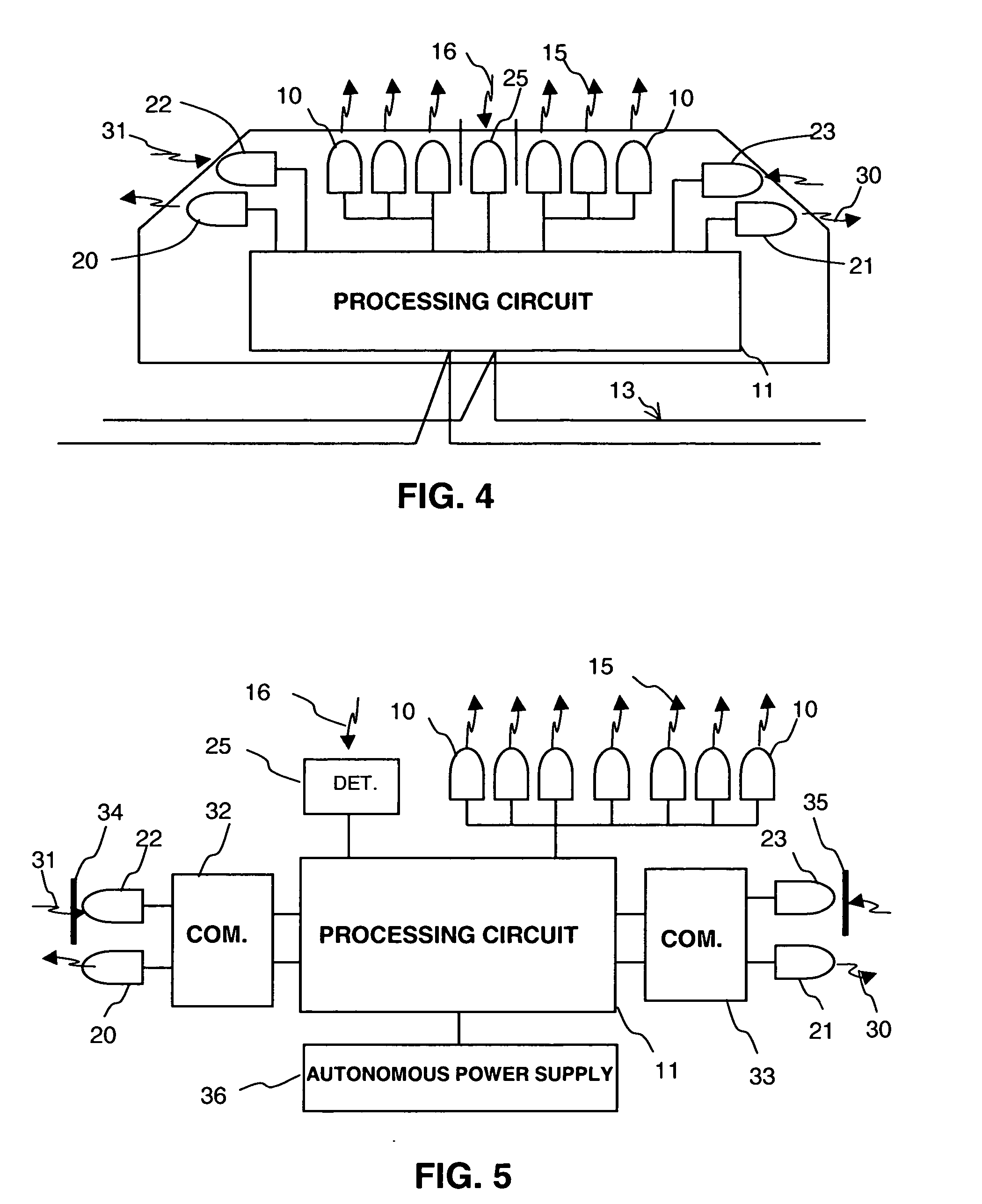
[0049] A ground marking device represented in FIG. 4 comprises a light source 10 controlled by a processing circuit 11. To control lighting of said light source, the processing circuit receives electric power supplied by a power supply line 13. According to an embodiment of the invention, the marking device comprises communication means and detection means connected to the processing circuit.

[0050] The communication means are represented by emitters such as light-emitting diodes 20 and 21 and receivers such as receiver diodes 22 and 23 connected to the processing circuit 11. The receiver diode 22 can receive a switch-on control signal of the light source supplied by another marking device. For example, a lighting control signal can be emitted by a previous marking device in an installation scheduled for sequential lighting of the marking devices.

[0051] The detection means enable the presence, movement or passage of an object to be detected. They are represented by an optic detecto...


PUM


Abstract

The marking device comprises a light source and a processing circuit to control lighting of said light source. Said device comprises an optic communication having at least one optic emitter and/or one optic receiver connected to the processing circuit. A detector detects the presence, movement or passage of an object. Said detector is connected to the processing circuit to control the optic communication according to signals supplied by said detector. A marking installation comprises marking devices arranged for example on a section of runway for an airport for guiding aircraft, or on a section of road to perform road signalling. The marking process enables the marking devices to be switched on by optic means according to detections.

Description

BACKGROUND OF THE INVENTION [0001] The invention relates to a ground marking device comprising a light source and a processing circuit to control lighting of said light source. The invention also relates to a marking process. The invention also relates to a ground marking installation for an airport or aerodrome comprising at least two marking devices arranged on a portion of runway for guiding planes. The invention also relates to a marking installation for a road section comprising at least two marking devices arranged on a portion of road to perform road signalling. STATE OF THE ART [0002] Ground marking devices are used in particular to guide aircraft on portions of runways in airports or vehicles on road sections. As represented in the diagram of FIG. 1, state of the art marking devices generally comprise lighting beacons or lamps 1 controlled individually, in a group, simultaneously or sequentially by an electric control circuit 2. [0003] In more complex processes, represented...

Claims


Application Information

Patent Timeline
IPC IPC(8): H05B37/02H05B37/03
CPCH05B37/0227Y02B20/44H05B37/034H05B37/0272H05B47/115H05B47/195H05B47/22Y02B20/40
Inventor LOVATO, JEAN-LOUISCOLLOMB, VIRGINIEMINIER, VINCENT
Owner SCHNEIDER ELECTRIC IND SAS
Why Eureka
Try Eureka