Bridge expansion joint device

A technology of expansion joints and bridges, applied in bridges, bridge parts, bridge construction, etc., can solve the problems of broken bolts, non-existence, old ones and new ones, increased bridge maintenance costs, etc., and achieves the effect of convenient installation and replacement

Inactive Publication Date: 2016-04-20
常熟市双惠路桥工程构件有限公司
View PDF12 Cites 16 Cited by
  • Summary
  • Abstract
  • Description
  • Claims
  • Application Information

AI Technical Summary

Problems solved by technology

[0004] Although not limited to the patents enumerated above, although each has corresponding technical effects, there are the following disadvantages: one, because the comb-tooth plate support beam (such as the "track member" referred to in CN1548655A and the "edge beam" referred to in CN204570468U ) directly through the anchor bar (CN1548655A called "connector") and the post-cast concrete as a whole, and the post-cast concrete is combined with the bridge girder body (also called abutment) and the road surface layer, so the bridge deck and the abutment are heated During the process of expansion and contraction, it is easy to produce a shearing effect on the bolts used to fix the comb plate and the support frame of the comb plate (that is, the fixing bolts of the comb plate, the same below), and even cause the bolt to break, and once the bolt breaks, The comb plate is in an unregulated state, and the aforementioned advantages of the bridge expansion joint device no longer exist, so the old ones can only be discarded and replaced with new ones. On the one hand, it increases the difficulty of management and maintenance of the bridge management department, and on the other hand, it increases the maintenance cost of the bridge. ; secondly, due to structural design reasons, it is inconvenient to install and replace the waterstop; thirdly, because a large amount of welding work needs to be done on the installation or laying site, it not only increases the on-site construction workload, but also cannot reflect the factory high-efficiency manufacturing requirements

Method used


Image

  • Bridge expansion joint device
  • Bridge expansion joint device

Examples


Embodiment

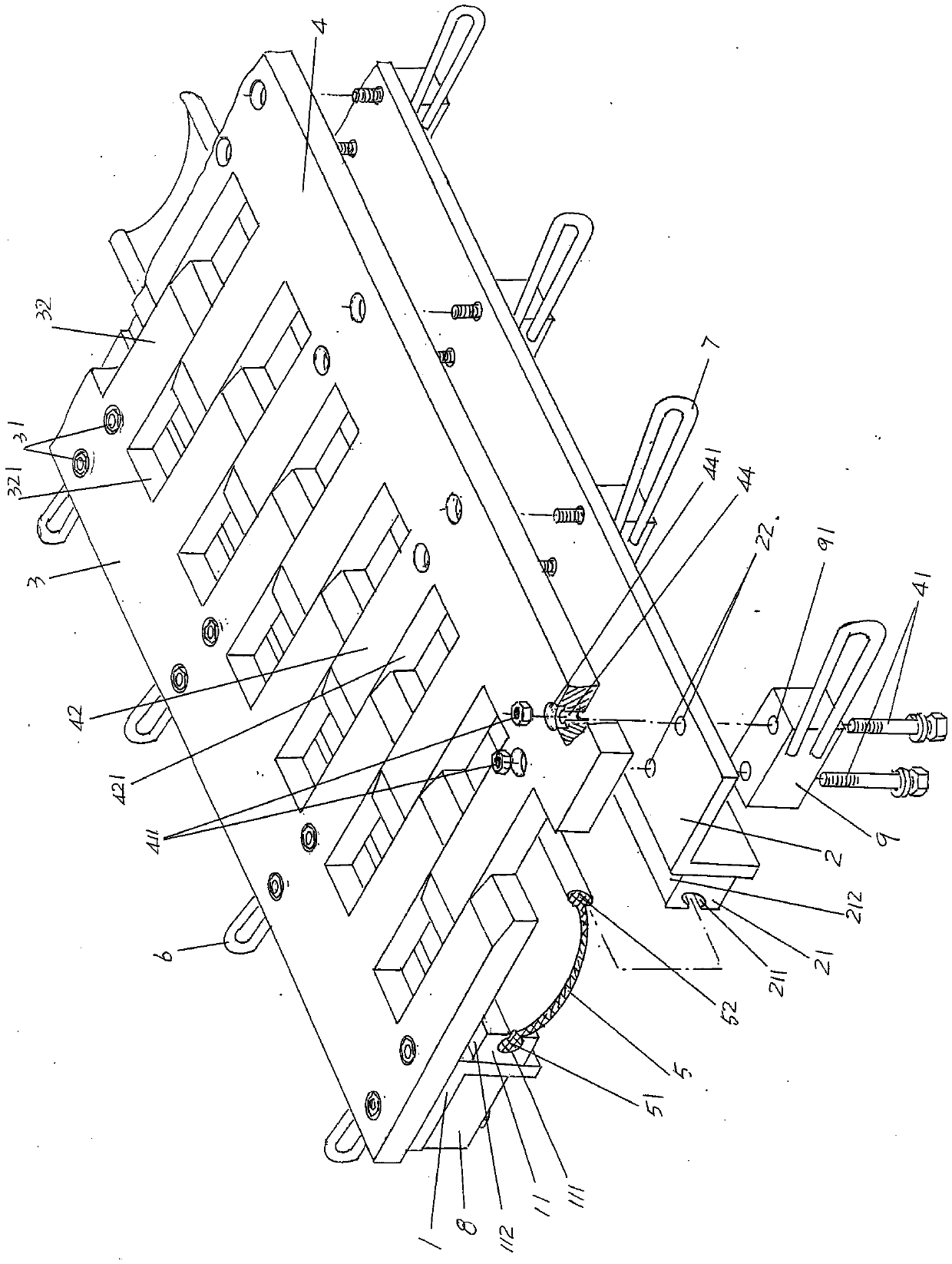
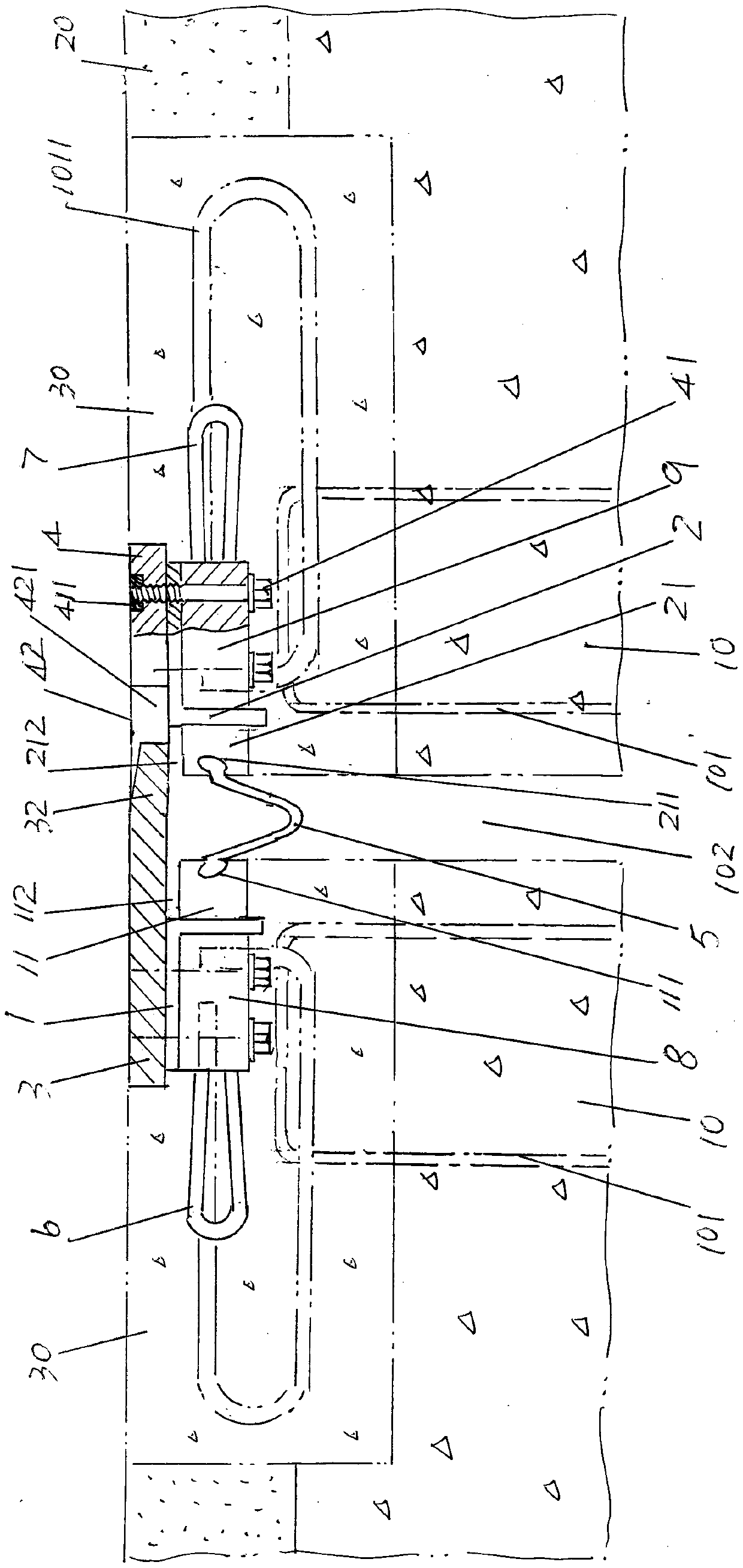
[0021] See figure 1 , showing the left comb plate support beam 1, the right comb plate support beam 2, the left comb plate 3, the right comb plate 4, the water stop 5, the left anchor rib 6 and the right anchor rib 7, the left comb The plate support beam 1 and the right comb-tooth plate support beam 2 are kept parallel to each other in the length direction, and the left comb-tooth plate 3 is fixed to the left comb-tooth plate support beam 1 by two rows of left comb-tooth plate fixing bolts 31 distributed at intervals. The length direction of the left comb tooth plate 3 is formed with left comb teeth 32, and the space between each two adjacent left comb teeth 32 constitutes a right comb tooth matching cavity 321, and the right comb tooth plate 4 is distributed by two rows in an interval state. The right comb tooth plate fixing bolt 41 is fixed with the right comb tooth plate support beam 2, and the right comb tooth 42 is formed in the length direction of the right comb tooth pl...


PUM


Abstract

The invention belongs to the technical field of bridge auxiliary members, and relates to a bridge expansion joint device. The bridge expansion joint device comprises left and right comb plate supporting beams, left and right comb plates, a water stop belt, left anchor bars and right anchor bars and further comprises a set of left supporting blocks and a set of right supporting blocks, wherein the set of left supporting blocks are distributed at intervals in the length direction of the left comb plate supporting beam and fixed through left comb plate fixing bolts, and the set of right supporting blocks are distributed at intervals in the length direction of the right comb plate supporting beam and fixed through right comb plate fixing bolts; a left water stop belt embedding base is fixed to one side, facing the right comb plate supporting beam, of the left comb plate supporting beam, a right water stop belt embedding base is fixed to one side, facing the left comb plate supporting beam and corresponding to the left water stop belt embedding base, of the right comb plate supporting beam, and the water stop belt is embedded between the left water stop belt embedding base and the right water stop belt embedding base. It is avoided that shear force on bolts of the left and right comb plates is generated in the heat expansion and cold contraction process of a bridge floor and a bridge abutment, the water stop belt is convenient to install and replace, operation intensity is relieved, and construction efficiency is improved.

Description

technical field [0001] The invention belongs to the technical field of bridge auxiliary components, and in particular relates to a bridge expansion joint device. Background technique [0002] As is well known in the industry, due to environmental temperature changes and other reasons, objects will expand with heat and contract with cold (thermal expansion and contraction are also called expansion and contraction). Beam joints are set between adjacent bridge decks, and the beam joints are expansion joints. Bridge expansion joint devices are installed between the beam joints at positions corresponding to the beam joints. The expansion joint devices have at least the following advantages: first, reduce Noise generated when vehicles pass; second, to improve the comfort of driving, otherwise it will cause bumps and even safety accidents; third, to prevent sundries and rainwater invasion; fourth, to improve the integrity and visual effect of the bridge deck. [0003] There is a l...

Claims


Application Information

Patent Timeline
Patent Type & Authority Applications(China)
IPC IPC(8): E01D19/06
CPCE01D19/06
Inventor 薛根荣
Owner 常熟市双惠路桥工程构件有限公司
Why Eureka
Try Eureka