Explosion-proof and safety-increased type composite explosion-proof motor with current transformer

A technology for current transformers and explosion-proof motors, which is applied to electrical components, electromechanical devices, and electric components, etc., can solve the problem of high cost of pre-purging devices and positive pressure control devices, high construction materials and labor costs, and reduced motor operation reliability. and other problems, to achieve the effect of light weight, improved connection reliability and simple structure

Active Publication Date: 2016-04-20
WOLONG ELECTRIC NANYANG EXPLOSION PROTECTION GRP CO LTD
View PDF7 Cites 4 Cited by
  • Summary
  • Abstract
  • Description
  • Claims
  • Application Information

AI Technical Summary

Problems solved by technology

Both the increased safety motor and the positive pressure explosion-proof motor need to provide compressed air for the motor, and long-distance air pipes need to be laid. The cost is high, which directly increases the manufacturing cost of the motor. At the same time, the circuit of the pre-purge device or the positive pressure control device is complicated, and there are many electronic control components. Once there is a problem with the circuit, it will cause the motor to stop unexpectedly
The pre-purge device or positive pressure control device has high requirements on the pressure stability of the compressed air. Once the pressure of the compressed air fluctuates greatly, the pre-purge device or positive pressure control device will send an alarm signal remotely, causing the motor to stop unexpectedly, reducing the The operational reliability of the motor

Method used


Image

  • Explosion-proof and safety-increased type composite explosion-proof motor with current transformer
  • Explosion-proof and safety-increased type composite explosion-proof motor with current transformer
  • Explosion-proof and safety-increased type composite explosion-proof motor with current transformer

Examples


Embodiment Construction

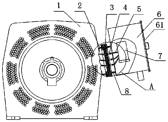
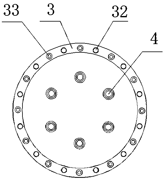
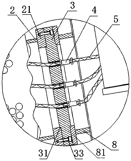
[0019] see Figure 1-3 , the explosion-proof+increased-safety composite explosion-proof motor with current transformer of the present invention includes a flameproof motor body 1, and an annular junction box support 2 is welded on the frame of the flameproof motor body 1, and the junction box supports A flameproof cover 3 is provided on the seat 2, and an increased safety current transformer junction box 6 is connected to the flameproof cover 3 through a junction box seat 8. The flameproof cover 3 is provided with a flameproof gland 4 , the motor lead 5 in the flameproof motor body 1 is connected to the conductive member 7 inside the junction box 6 through the flameproof gland 4, the junction box support 2, the flameproof cover plate 3 and the flameproof The gland head 4 and the machine base together form the flameproof enclosure of the motor, which isolates the inside of the motor from the junction box 6 of the increased safety current transformer, and realizes the effective ...


PUM


Abstract

The invention discloses an explosion-proof and safety-increased type composite explosion-proof motor with a current transformer. An annular junction box support is welded on the base of an explosion-proof motor body. The annular junction box support is provided with an explosion-proof cover plate. The explosion-proof cover plate is connected with a safety-increased type current transformer junction box via a terminal box base. The explosion-proof cover plate is provided with an explosion-proof cable joint. The terminal box base, the explosion-proof cover plate, the explosion-proof cable joint and the base together form an explosion-proof housing of the motor. In this way, through arranging the current transformer as a measurement element on the explosion-proof motor body for realizing the differential protection, the interphase short-circuit protection function is effectively realized. Therefore, the security level of the explosion-proof motor is effectively realized. The motor is simple in structure, convenient to install and maintain, good in security and reliability and high in explosion-proof level. The technical scheme of the invention can be effectively applied to the explosion-proof motor with the power thereof larger than 2000 kW. The cost of the motor is greatly reduced.

Description

technical field [0001] The invention belongs to the technical field of motors, in particular to a flameproof + increased safety composite explosion-proof motor with a current transformer. Background technique [0002] The raw materials and products in the petrochemical industry contain a large amount of flammable and explosive substances. According to the requirements of explosion-proof regulations, the motors driving chemical equipment need to use flameproof, increased safety and positive pressure explosion-proof motors. With the enlargement of petrochemical installations, the power of the explosion-proof motors used is also increasing, and the requirements for the explosion-proof safety level of the explosion-proof motors are also getting higher and higher. [0003] Explosion-proof motor is the key equipment of petrochemical plant, its failure will seriously affect the normal operation of the plant and cause huge economic losses. In the possible faults of the motor, the p...

Claims


Application Information

Patent Timeline
Patent Type & Authority Applications(China)
IPC IPC(8): H02K5/136H02K5/22
CPCH02K5/136H02K5/225
Inventor 张运生余志鹏刘彦华赵岩李金玉姚金艳甘方熹于树坤
Owner WOLONG ELECTRIC NANYANG EXPLOSION PROTECTION GRP CO LTD
Why Eureka
Try Eureka