Gear system for a twin-screw extruder

A twin-screw extruder and transmission technology, applied in transmission, gear transmission, mechanical equipment, etc., can solve the problems of ring gear deformation and disadvantage, avoid shear force and elastic deformation, and achieve high operational safety. Effect

Inactive Publication Date: 2008-11-05
THEYSOHN EXTRUSIONSTECHNIK GMBH
View PDF3 Cites 5 Cited by
  • Summary
  • Abstract
  • Description
  • Claims
  • Application Information

AI Technical Summary

Problems solved by technology

Considering that the ring gear deforms elastically, the situation becomes even more unfavorable

Method used


Image

  • Gear system for a twin-screw extruder
  • Gear system for a twin-screw extruder
  • Gear system for a twin-screw extruder

Examples


Embodiment Construction

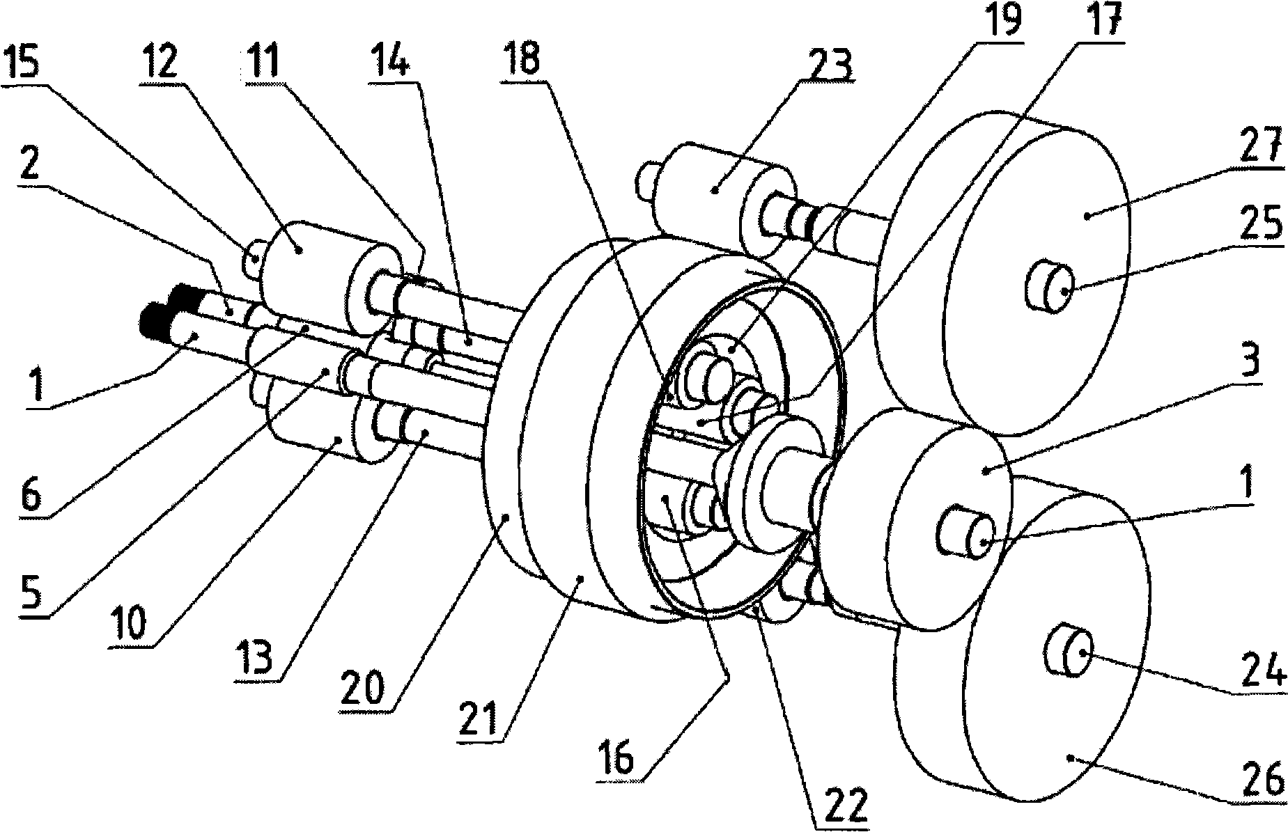
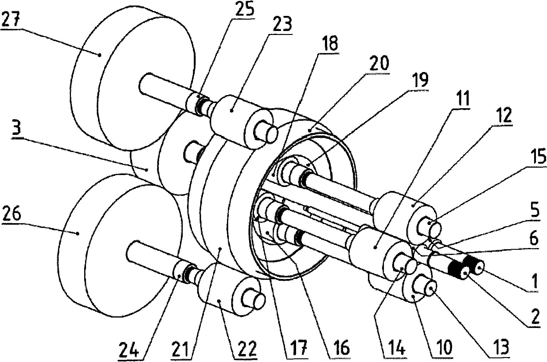
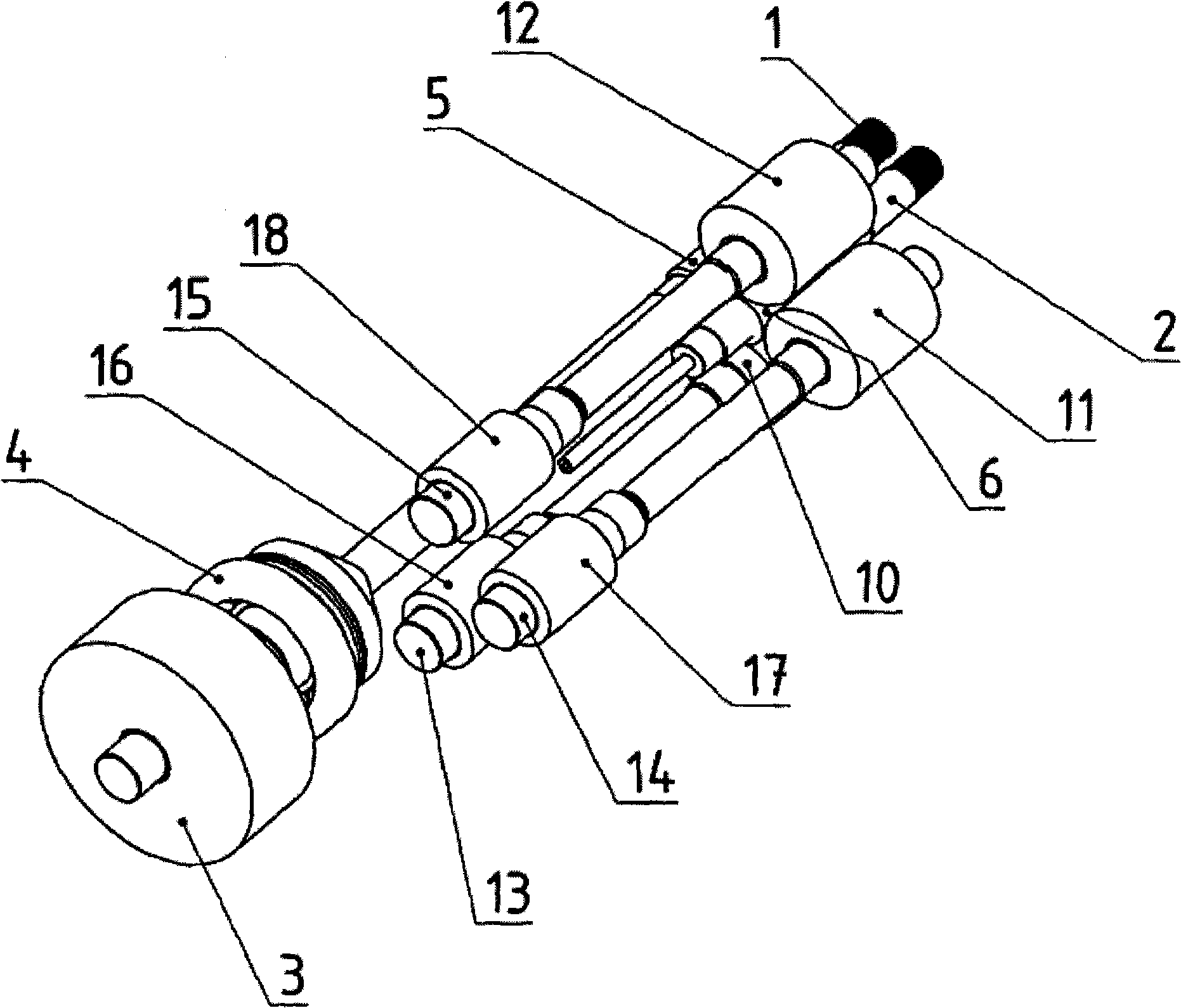
[0020] The drive gear 3 is rotatably fixed on the long drive shaft 1 and meshes with the output gear of a motor not shown in the figure, or the long drive shaft 1 is directly connected with the drive motor. In addition, the long drive shaft 1 carries an axial bearing 4 and is rotatably fixed to a gear 5 that meshes with a gear 6 rotatably fixed to the short drive shaft 2. The short drive shaft 2 also has an axial bearing 9. Since the long drive shaft 1 is relatively close, the diameter of the axial bearing 9 is limited, and it is preferably designed as a double row bearing.

[0021] Gear 5 and gear 6 have helical gear teeth. The helical gear transmission is selected so that the short drive shaft 2 is pushed toward the screw, so the axial force acting on the bearing 9 of the short drive shaft 2 decreases proportionally with the increase of the torque. Therefore, the axial force on the long drive shaft 1 does increase, but this is not a problem because the axial bearing 4 can be mad...


PUM


Abstract

Gear system for driving screws of a twin-screw extruder with two parallel drive shafts (1, 2) of different length, of which the longer drive shaft (1) bears a drive gear wheel (3). The shorter drive shaft (2) has rotationally fixed connection by way of a pinion (6) to three distributor shafts (13, 14, 15), which can be driven from the longer drive shaft (1) by way of an annular gear wheel (20) which has internal teeth (19) and, on the distributor shafts (13, 14, 15), gear wheels (16, 17, 18) intermeshing with these teeth. On the longer drive shaft (1), there is a pinion (5) directly intermeshing with the pinion (6) of the shorter drive shaft (2). In order to achieve good division of the loads, the annular gear wheel (20) also has outer teeth (21) which intermesh with gear wheels (22, 23) of two intermediate shafts (24, 25), which intermesh by way of further gear wheels (26, 27) with the drive gear wheel (3).

Description

Technical field [0001] The invention relates to a transmission device according to the preamble of claim 1. Background technique [0002] The problem with driving a twin-screw extruder is that two drive shafts very close to each other must transmit very large torques. The lengths of the two drive shafts of the transmission are different. Almost any size drive gear can be placed on the long drive shaft, so that despite the large torque, the force acting on the drive gear (the result of its larger diameter) can be kept within a reasonable range. Only gears with a relatively small diameter can be placed on the short drive shaft, otherwise it will interfere with the long drive shaft. The force acting on the gear is very large and has a large torque. Only a limited way can be used to lengthen the gear (in the longitudinal direction of the drive shaft) to reduce the pressure on the teeth of the gear, but because the drive shaft will be twisted under high torque, only a part of the leng...

Claims


Application Information

Patent Timeline
Patent Type & Authority Applications(China)
IPC IPC(8): B29C47/08F16H1/22B29C48/03
CPCB29C47/0009Y10T74/19098F16H1/227B29C47/0801B29C48/03B29C48/252F16H1/22
Inventor E·施纳布尔
Owner THEYSOHN EXTRUSIONSTECHNIK GMBH
Why Eureka
Try Eureka