Vacuum pump

A vacuum pump, fixed vane technology, used in pumps, pump components, axial flow pumps, etc.

Active Publication Date: 2014-09-10
SHIMADZU SEISAKUSHO CO LTD
View PDF6 Cites 1 Cited by
  • Summary
  • Abstract
  • Description
  • Claims
  • Application Information

AI Technical Summary

Problems solved by technology

To provide a new vacuum pump, the technical problem to be solved is to suppress the deformation of the fixed blades during assembly due to overlapping or warping of the divided fixed blades at the butt joint, which is very suitable for practical use.

Method used


Image

  • Vacuum pump
  • Vacuum pump
  • Vacuum pump

Examples


Embodiment approach 1

[0065] Hereinafter, the vacuum pump of the present invention will be described by taking a turbomolecular pump as one embodiment with reference to the drawings.

[0066] (The overall structure of the vacuum pump)

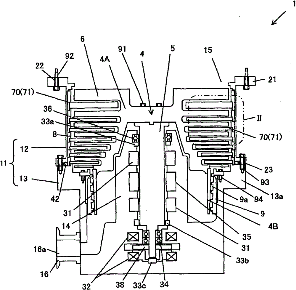
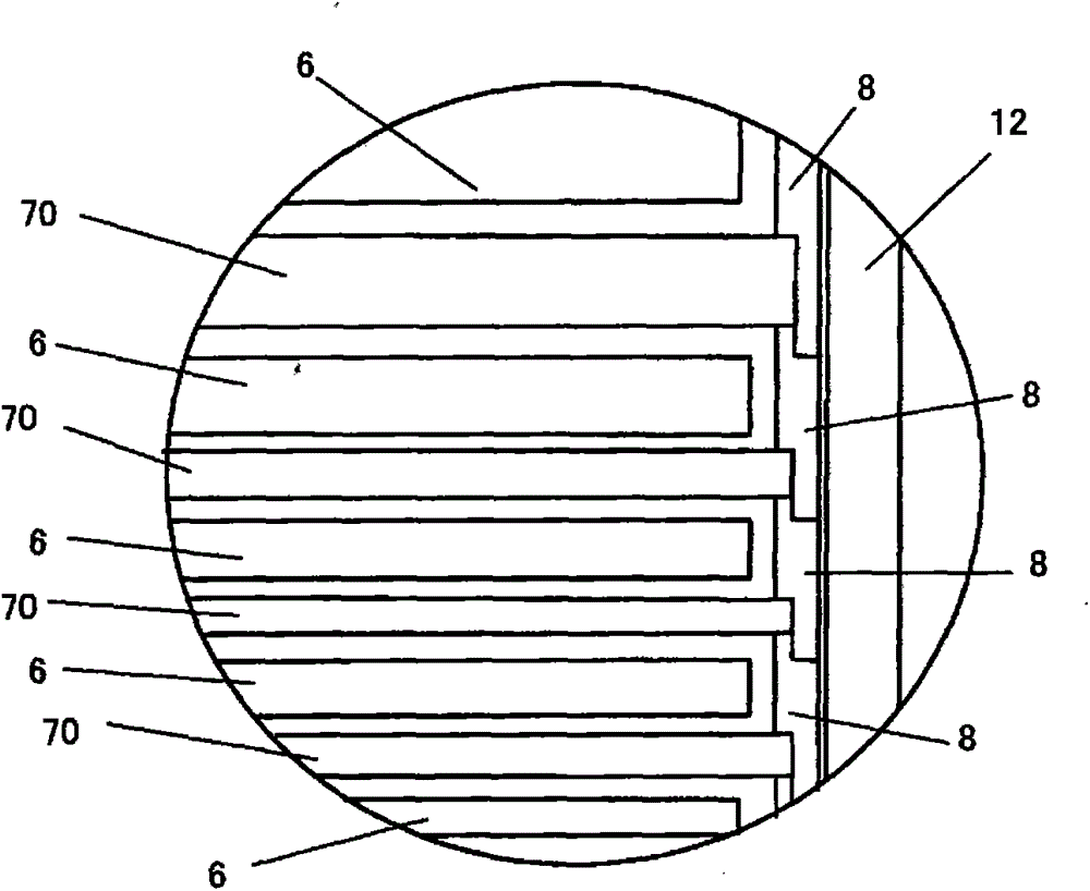
[0067] figure 1 is a cross-sectional view of the turbomolecular pump 1, figure 2 yes figure 1 Magnification of region II in .

[0068] The turbomolecular pump 1 includes a pump housing 11 formed of a casing member 12 and a base 13 fixed to the casing member 12 .

[0069] The casing member 12 has a substantially cylindrical shape, is formed of, for example, SUS, and has an upper flange 21 formed at an upper end thereof. A circular intake port 15 is formed inside the upper flange 21 of the case member 12 . Through-holes 22 for bolt insertion are formed in the upper flange 21 at approximately equal intervals in the circumferential direction. The turbomolecular pump 1 is an external device mounted on a semiconductor manufacturing device or the like after the bolt...

Embodiment approach 2

[0117] Figure 11 It is a sectional view of Embodiment 2 of the main part of the stationary blade part of this invention.

[0118] Embodiment 2 differs from Embodiment 1 in the following points.

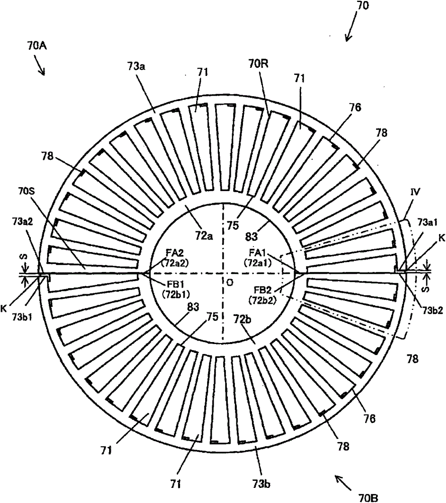
[0119] (1) In the divided fixed blade portion 70A and the divided fixed blade portion 70B, the outer peripheral side support portion 76A connecting the stator blade 71 to the outer peripheral rim 73 a and the outer peripheral rim 73 b extends over the inner peripheral side support portion 75 similarly to the inner peripheral side support portion 75 . The entire length of the outer peripheral end portion 71So of the stator blade 71 is formed. That is, the opening portion 78 formed in Embodiment 1 for separating the front end side portion 77 from the outer peripheral side support portion 76 is not included.

[0120] (2) On the inner peripheral rim 72a and the inner peripheral rim 72b of the divided fixed blade portion 70A and the divided fixed blade portion 70B, there are respectivel...

Embodiment approach 3

[0128] Figure 12 It is a cross-sectional view of Embodiment 3 of the main part of the stationary blade part of the present invention.

[0129] Embodiment 3 differs from Embodiment 1 in the following points.

[0130] (1) In the divided fixed blade portion 70A and the divided fixed blade portion 70B, the outer peripheral side support portion connecting the outer peripheral side end portion 71So of the stator blade 71 to the outer peripheral rim 73 a and the inner peripheral side support portion of the stator blade 71 are not included. The end portion 71Si is an inner peripheral support portion connected to the inner peripheral rim 72a. That is, the outer peripheral end 71So and the inner peripheral end 71Si of each stator blade 71 are separated from the outer peripheral rim 73a, the inner peripheral rim 72a, or the inner peripheral rim 72b, and the outer peripheral rim 73b over the entire length, respectively.

[0131] (2) Among the divided fixed blade portion 70A and the div...


PUM


Abstract

The invention provides a vacuum pump to suppress deformation of a stationary blade portion when assembled due to the fact that overlap or warpage is generated in an abutting portion when the stationary blade portion is divided. The stationary blade portion (70) is formed into a ring by abutting two radial abutting ends of divided stationary blade portions (70A, 70B). A cutout (K) formed by cutting a portion from an abutting surface in the circumferential direction is provided on an outer circumferential rim (73a) of the divided stationary blade portions (70A), and a gap (S) is formed between the outer circumferential rim (73a) of the divided stationary blade portions (70A) and one end (73b2) of an outer circumferential rim (73b) of the divided stationary blade portions (70B) when assembled.

Description

technical field [0001] The present invention relates to a vacuum pump including an exhaust section including a moving blade section and a fixed blade section. Background technique [0002] In a vacuum pump such as a turbo molecular pump (Turbo Molecular Pump), a rotor including movable blades arranged in multiple stages is rotated at high speed in the pump container, and the rotor passes between the movable blades and the stages arranged in the movable blades. The stationary blade part of the blade moves the gas molecules from the suction port side to the exhaust port side. [0003] The movable blade portion of each stage includes a rotor blade, and the fixed blade portion of each stage includes a stator blade (stator blade). Each stationary blade part is supported at predetermined intervals by the spacer arrange|positioned at the outer periphery of a stationary blade part. The fixed blade portion is formed into a wheel shape by combining a pair of half-divided annular mem...

Claims


Application Information

Patent Timeline
Patent Type & Authority Applications(China)
IPC IPC(8): F04D19/04
CPCF04D19/042F04D29/542
Inventor 住本慎
Owner SHIMADZU SEISAKUSHO CO LTD
Why Eureka
Try Eureka