network system
A network system and network technology, applied in the field of network systems with redundant structures, can solve problems such as network system failures, and achieve the effects of improving fault resistance, simple structure, and improving redundancy
- Summary
- Abstract
- Description
- Claims
- Application Information
AI Technical Summary
Problems solved by technology
Method used
Image
Examples
Embodiment approach 1
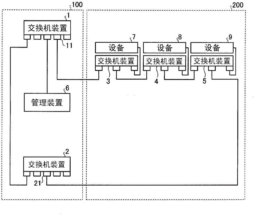
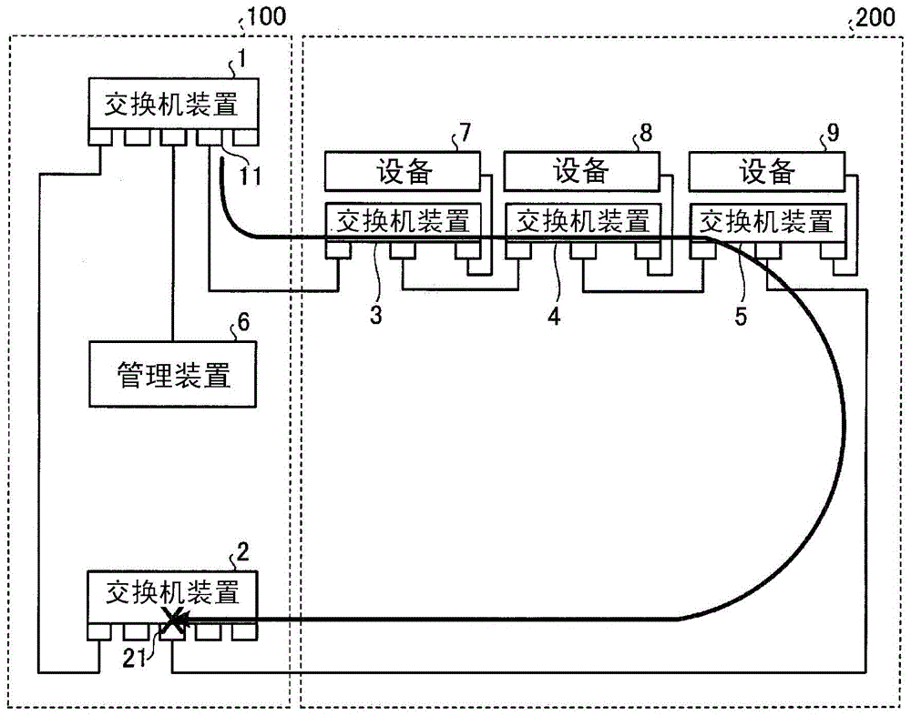
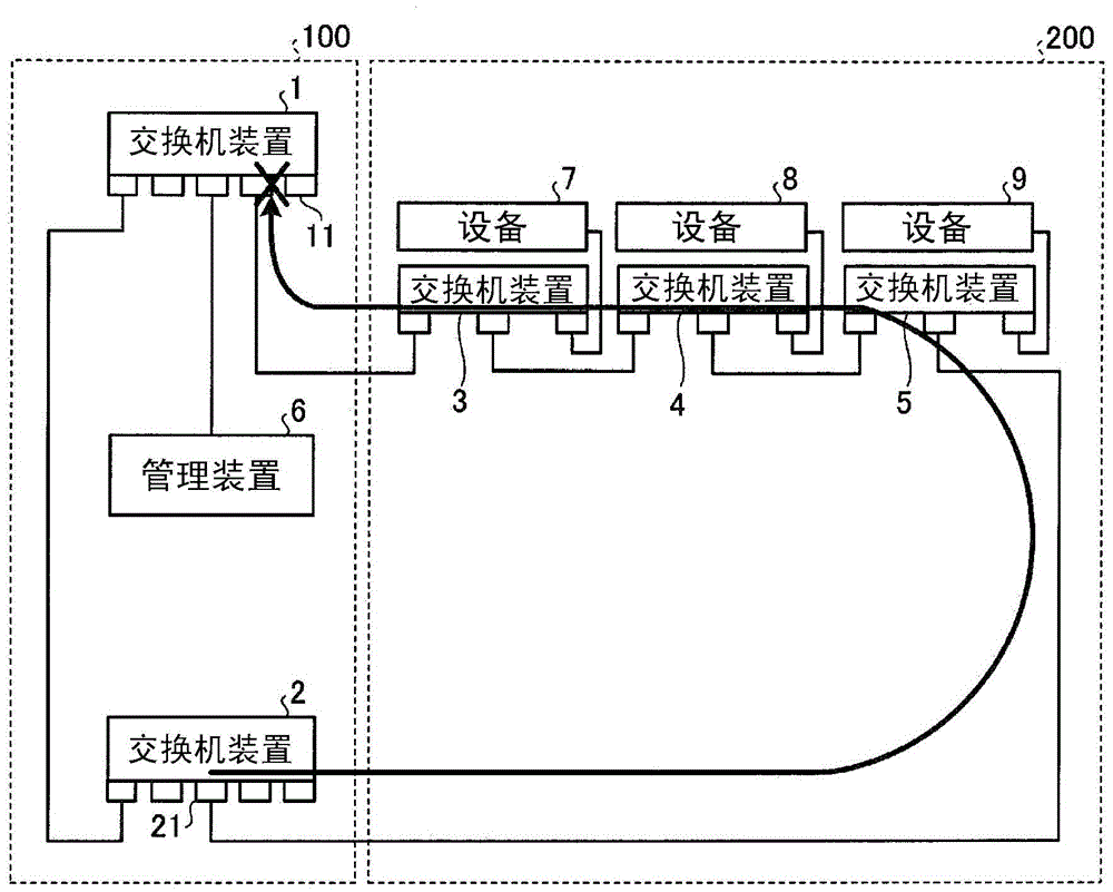
[0028] figure 1 It is a figure which shows the structural example of the network system of Embodiment 1. Such as figure 1 As shown, the network system of this embodiment includes a trunk network 100 and a sub-network 200 connected to the trunk network 100 at two places. The trunk network 100 includes switching devices 1 and 2 . Subnetwork 200 includes switching devices 3 - 5 . This subnetwork 200 is a linear network in which each switching device is arranged linearly (also referred to as a chain). The switch devices 1 to 5 are Ethernet (registered trademark) switches. In addition, the switching devices constituting the trunk network 100 are not limited to two. Three or more switch devices may constitute the trunk network 100 . Likewise, the number of switch devices constituting the subnetwork 200 is not limited to three.
[0029] The switch devices 3 and 5 positioned at both ends of the linear network comprise physical ports as endpoints of the linear network, the physi...
Embodiment approach 2
[0044] Figure 4 It is a figure which shows the structural example of the network system of Embodiment 2. In the network system of this embodiment, the network system described in Embodiment 1 (see figure 1 ) of the trunk network 100 is replaced by a trunk network 101. In this embodiment, only the parts different from Embodiment 1 will be described.
[0045] The trunk network 101 adds the switching device 10 to the trunk network 100 included in the network system according to the first embodiment. The switching device 10 is connected to the switching device 1 and the switching device 2, and the switching devices 1, 2, and 10 of the trunk network 101 form a loop. These switch devices 1, 2, and 10 correspond to the Ethernet ring protocol, and even if one switch device constituting the trunk network 101 fails, transmission of the trunk network other than the failed switch can be maintained.
[0046] One of the switch devices 1 and 2 disconnects when a packet of a specific log...
Embodiment approach 3
[0049] Figure 5 It is a figure which shows the structural example of the network system of Embodiment 3. In the network system of this embodiment, the network system described in Embodiment 1 (see figure 1 ) trunk network 100 is replaced by trunk network 100a. In this embodiment, only the parts different from Embodiment 1 will be described.
[0050] In the trunk network 100a, the switch devices 1 and 2 of the trunk network 100 included in the network system according to the first embodiment are replaced with the switch devices 1a and 2a. The connection relationship between the switching devices 1 a and 2 a is the same as that of the switching devices 1 and 2 in the first embodiment. In addition, the connection relationship between the main network 100a and the sub-network 200 is the same as the connection relationship between the main network 100 and the sub-network 200 in the first embodiment.
[0051] In the network system of this embodiment, the switching devices 1a an...
PUM
 Abstract
Description
Claims
Application Information
 - R&D
- Intellectual Property
- Life Sciences
- Materials
- Tech Scout
- Unparalleled Data Quality
- Higher Quality Content
- 60% Fewer Hallucinations
Browse by: Latest US Patents, China's latest patents, Technical Efficacy Thesaurus, Application Domain, Technology Topic, Popular Technical Reports.
© 2025 PatSnap. All rights reserved.Legal|Privacy policy|Modern Slavery Act Transparency Statement|Sitemap|About US| Contact US: help@patsnap.com


