Saw frame counterweight structure of stone sawing machine

A technology of stone sawing machine and sawing frame, which is applied in the direction of stone processing tools, stone processing equipment, manufacturing tools, etc. It can solve the problem of affecting the stability of the stone sawing machine and the stone sawing effect, the eccentric block is easy to generate noise and vibration, and the increase in stone sawing machine Production cost and other issues, to achieve the effect of simple and reasonable structure, small vibration and low production cost

Active Publication Date: 2016-05-18
HUOHUANG METAL MFG
View PDF8 Cites 0 Cited by
  • Summary
  • Abstract
  • Description
  • Claims
  • Application Information

AI Technical Summary

Problems solved by technology

However, in order to drive the saw frame to work smoothly, the eccentric block is made of heavy and bulky materials, which not only increases the production cost of the stone saw machine, but also requires a huge driving force to drive the eccentric block movement, so it is necessary to ensure that the motor Enough power can drive the movement of the eccentric block, which increases the working energy consumption of the stone saw machine, and the heavy and large eccentric block is easy to generate noise and vibration when it is in motion. The working environment will also loosen other components of the stone sawing machine, which will affect the stability of the overall structure of the stone sawing machine and the effect of sawing stones, and even endanger the lives of workers in severe cases.

Method used


Image

  • Saw frame counterweight structure of stone sawing machine
  • Saw frame counterweight structure of stone sawing machine
  • Saw frame counterweight structure of stone sawing machine

Examples


Embodiment Construction

[0018] The present invention will be further described below in conjunction with the accompanying drawings and embodiments.

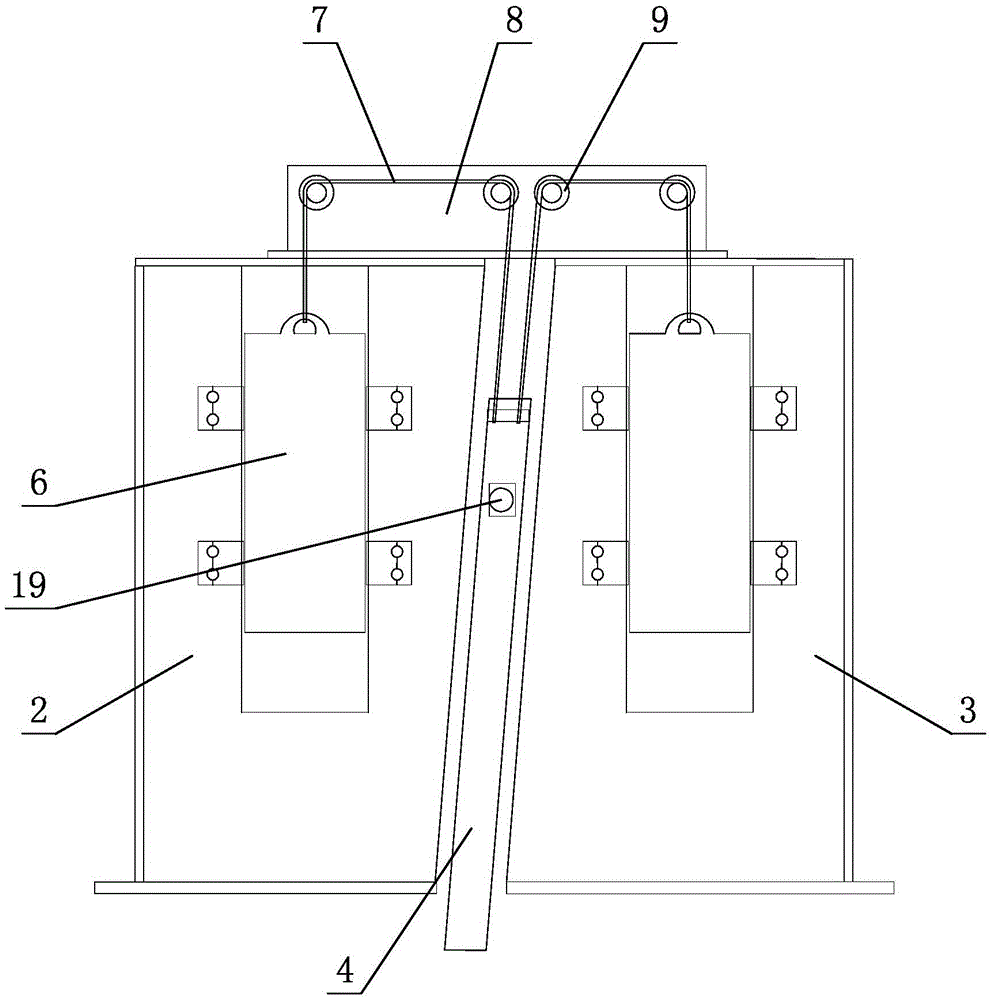
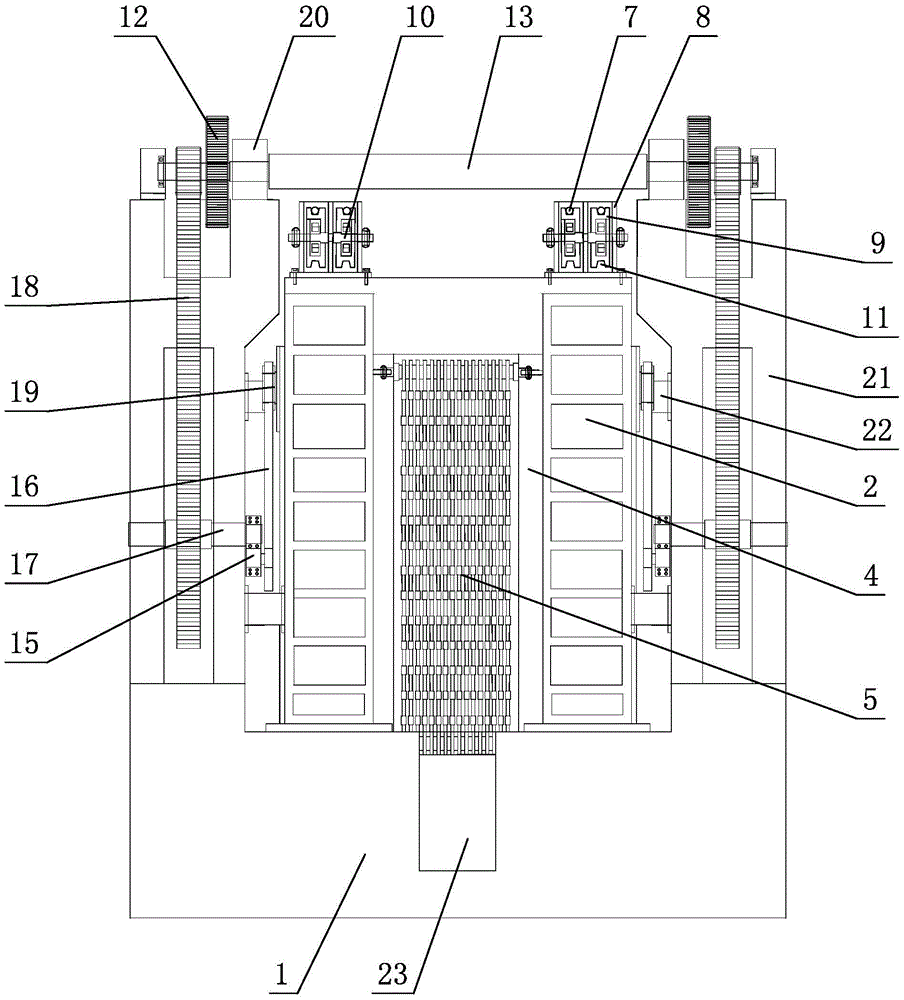
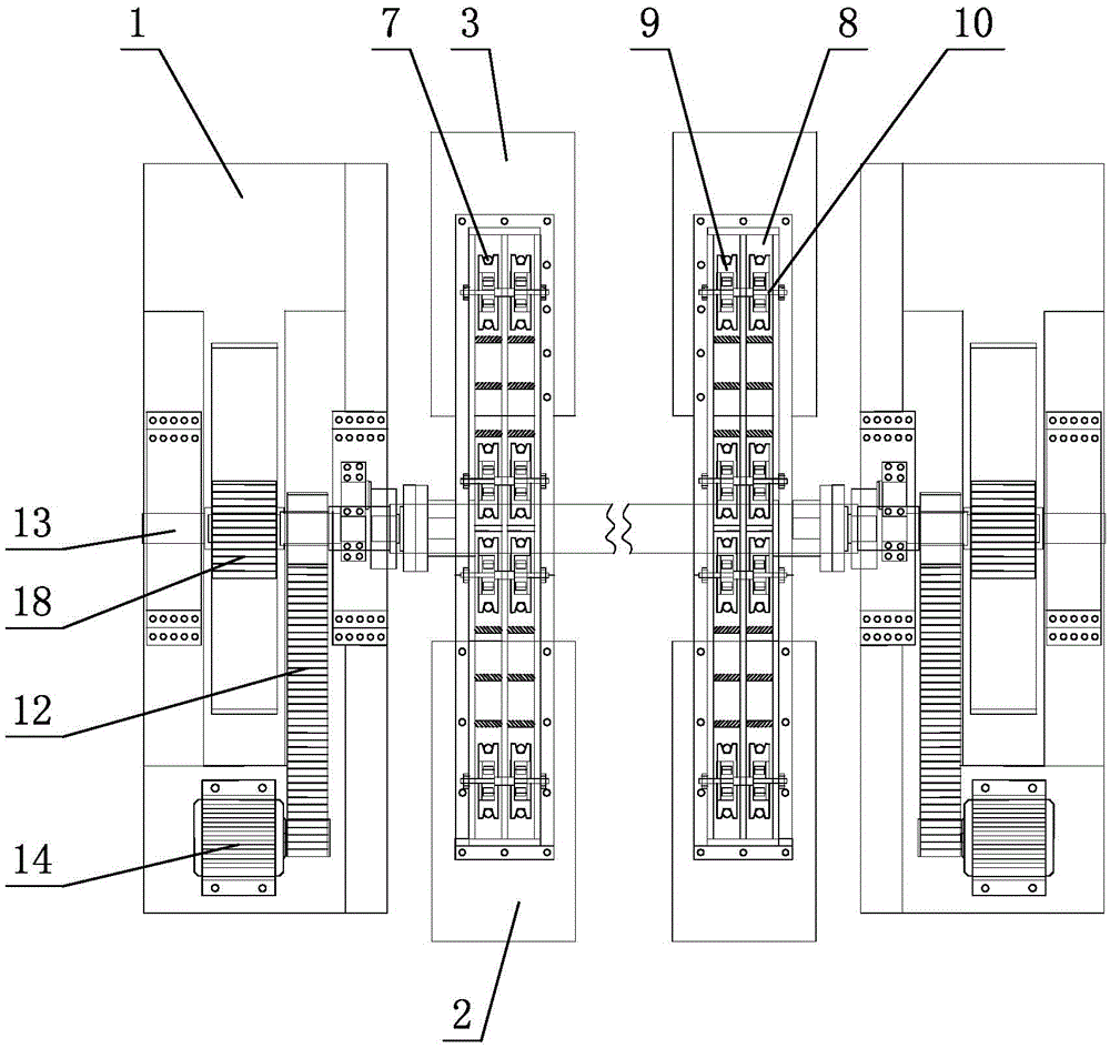
[0019] see Figure 1-Figure 3 , the saw frame counterweight structure of this stone sawing machine includes a base 1, and a front column 2 and a rear column 3 arranged on the base 1, a saw frame 4 is movable between the front and rear columns, and a saw frame 4 is provided with Several saw blades 5, the front column 2 and the rear column 3 are symmetrically arranged on the base 1, and a counterweight 6 is arranged on it; the saw frame 4 is connected with the counterweight 6 through a steel cable 7 , and move up and down between the front and rear columns through the transmission mechanism.

[0020] The inside of the front column 2 and the rear column 3 is provided with a cavity, and a counterweight 6 is placed in the cavity; the weight of the counterweight 6 is consistent with the weight of the saw frame 4 . The tops of the front column 2 and the rear...


PUM


Abstract

A saw frame weight balancing structure of a stone sawing machine comprises a base, and a front stand column and a rear stand column which are arranged on the base, wherein a saw frame is movably arranged between the front stand column and the rear stand column, a plurality of saw blades are arranged on the saw frame, the front stand column and the rear stand column are arranged on the base in a bilateral symmetry manner, weight balancing blocks are arranged on the front stand column and the rear stand column respectively, and the saw frame is in matched connection with the weight balancing blocks through steel cables and makes vertical to-and-forth movement between the front stand column and the rear stand column through a transmission mechanism. Through the improvement of the structure, the weight balancing blocks are arranged on the front stand column and the rear stand column respectively, the saw frame is in matched connection with the weight balancing blocks through the steel cables, and the weight of the weight balancing blocks is consistent with the weight of the saw frame, therefore the weight balancing blocks and the saw frame are in a balanced state, so that the vertical to-and-forth movement of the saw frame can be realized only by extremely small rotating speed and power of a driving motor, and while the vertical operation of the saw frame is enabled to be smoother, the rotating speed and power of the driving motor are effectively reduced by 2 / 3, accordingly, the manufacturing cost and the production cost of the stone sawing machine are reduced, and the practicability is high.

Description

technical field [0001] The invention relates to a stone sawing machine, in particular to a saw frame counterweight structure of the stone sawing machine. Background technique [0002] On September 7, 2011, I disclosed a main shaft structure of a large-scale stone sawing machine in Chinese Patent Document No. CN102172987A. The large-scale stone sawing machine includes a saw frame that slides up and down between the front column and the rear column, and the saw frame There are several saw blades / strips arranged on it, and the main transmission mechanism includes a main shaft connected to the saw frame, the main shaft is connected to the drive motor, and the main shaft is connected to the saw frame through an eccentric block and a connecting rod. The left and right sides of the saw frame are respectively connected to the drive motor through the main shaft, and the rotational speeds of the two main shafts are consistent. The main shaft is driven by the eccentric block and the c...

Claims


Application Information

Patent Timeline
Patent Type & Authority Patents(China)
IPC IPC(8): B28D1/02
Inventor 周炎群
Owner HUOHUANG METAL MFG
Why Eureka
Try Eureka