driver ic

A driver and drive circuit technology, applied in the direction of instruments, static indicators, etc., can solve the problems of image quality deterioration and brightness difference, and achieve the effect of preventing image quality deterioration.

Active Publication Date: 2019-04-23
SYNAPTICS JAPAN GK
View PDF1 Cites 0 Cited by
  • Summary
  • Abstract
  • Description
  • Claims
  • Application Information

AI Technical Summary

Problems solved by technology

[0008] However, the inventors of the present invention have found that when the frame period is lengthened using the above-mentioned low-leakage panel, the period during which the offset polarity is switched and held in order to cancel the above-mentioned offset becomes longer, and it is easy to recognize that each Brightness difference due to polarity switching, resulting in poor image quality
That is, if the polarity of the offset is switched in accordance with the display line cycle, the longer the frame cycle is, the longer the period for maintaining the luminance information rewritten in each display line cycle is. Therefore, each time the polarity is switched due to The difference in brightness due to the difference in offset is easily recognized in units of display lines, and as a result, the image quality deteriorates

Method used


Image

  • driver ic
  • driver ic
  • driver ic

Examples


Embodiment Construction

[0028] 1. Outline of Embodiment

[0029] First, an outline of the embodiments disclosed in the present application will be described. In the summary description of the embodiment, the reference numerals in the drawings referred to in parentheses are only elements included in the concept of the constituent elements to which the numerals are added.

[0030] [1]

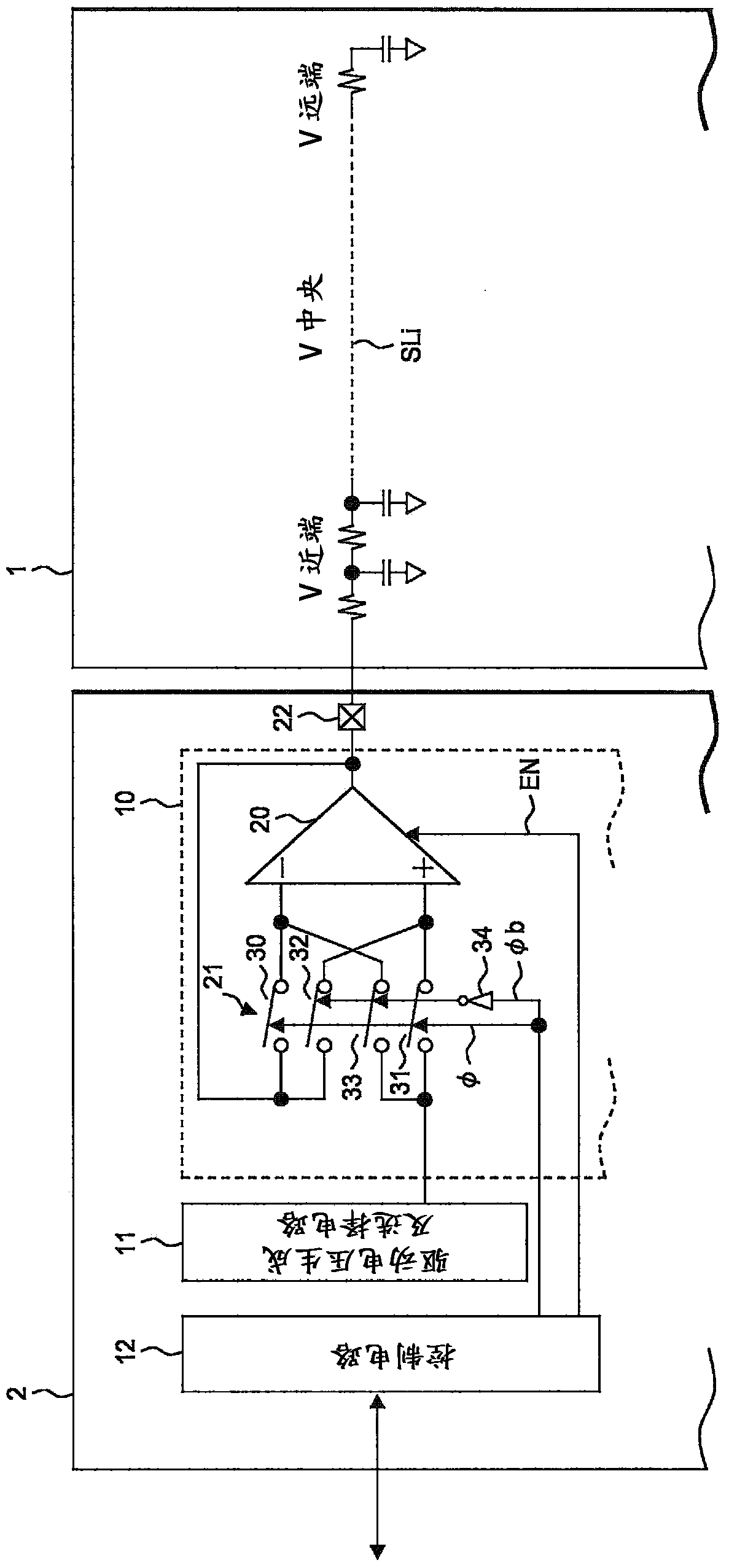
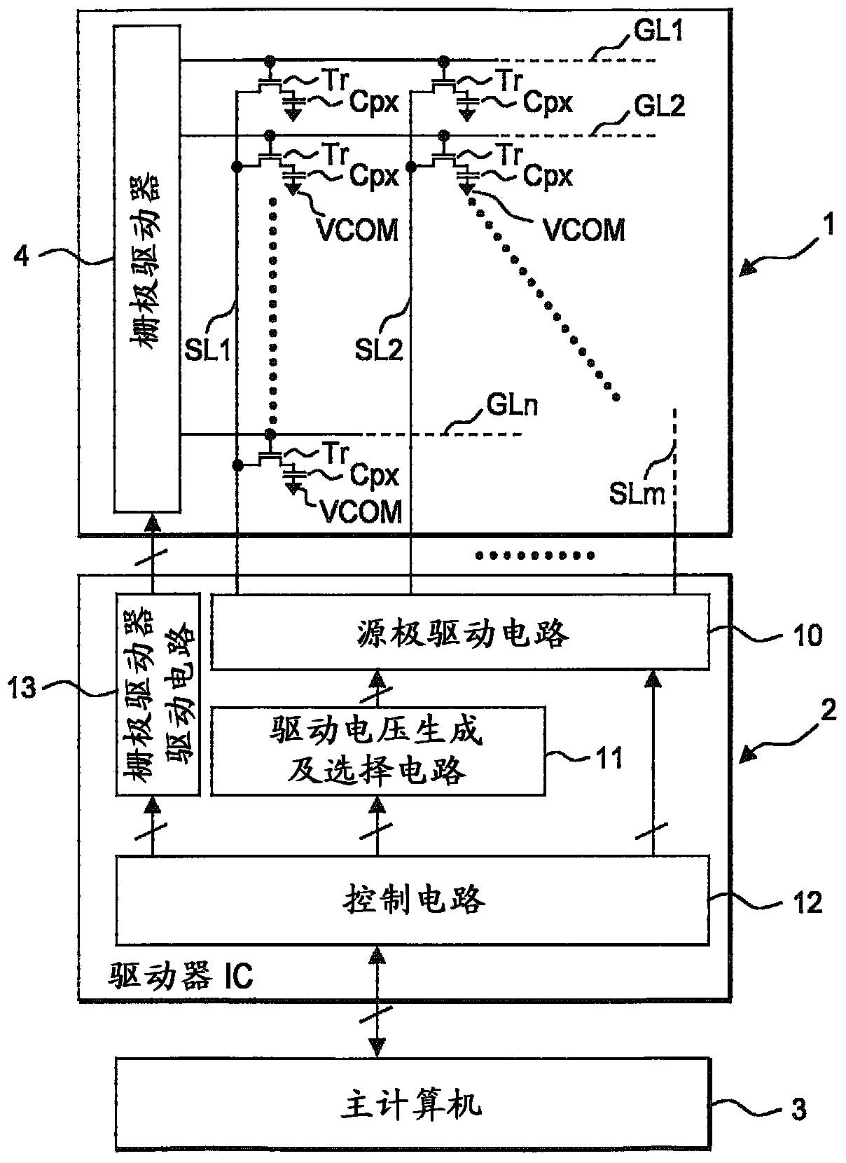
[0031] A driver IC (2, 2A) having a driving circuit (10, 10A) for driving the display panel (1), in which a pair of the aforementioned driving circuits The input of the differential input terminal is alternately switched multiple times between the gray scale voltage and the reference voltage.

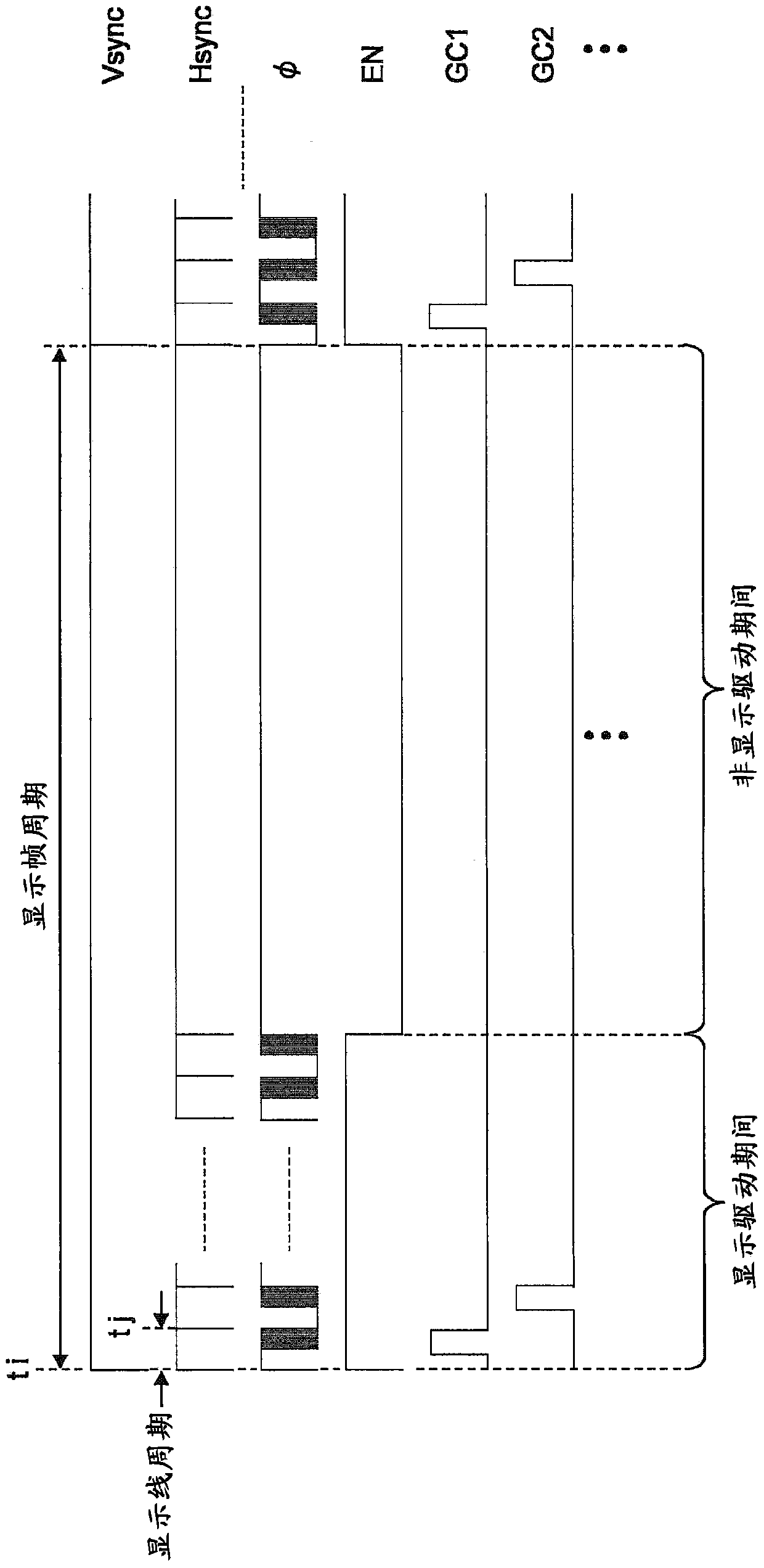
[0032] Thus, since the differential input applied to the drive circuit is alternately switched within one display line, that is, the operation of switching the polarity of the shift that occurs in the output due to the unbalanced differential input characteristics of the drive circuit is performed. multiple times, so that the...


PUM


Abstract

For each display line cycle, inputs to a pair of differential input terminals of a driving circuit are alternately switched in a cycle shorter than the display line cycle between a gradation voltage and a reference voltage. According to this, a chopping operation of switching polarities of offset appearing at the output of the driving circuit within one display line is performed for a plurality of times, and accordingly, a pixel of each display line maintains brightness information in which the chopping operation is already performed. As a result, although a frame cycle is lengthened, it is difficult to visually recognize a brightness difference caused by the offset.

Description

technical field [0001] The present invention relates to a driver IC for operating a display panel, and more particularly to a control technique for a drive circuit that drives a source line of a liquid crystal panel in units of display lines, for example, to a technique effectively applied to driving a low-leakage liquid crystal panel. Background technique [0002] If there is an undesired input offset in the differential amplifier circuit that drives the electrodes of the display panel, it appears in the amplified output causing the display to flicker. In Patent Document 1, there is a description of a drive control method in which the display screen is erased by switching the signals supplied to the inverting input terminal and the non-inverting input terminal of the differential amplifier circuit based on the display frame period and the display line period. The influence of the offset voltage between consecutive display lines, wherein the differential amplifier circuit dr...

Claims


Application Information

Patent Timeline
Patent Type & Authority Patents(China)
IPC IPC(8): G09G3/36
CPCG09G3/3688G09G3/3614G09G2310/0291G09G2320/0247
Inventor 高荷敏行立花利一纳富志信秋叶武定
Owner SYNAPTICS JAPAN GK
Why Eureka
Try Eureka